Not logged inAmerican Welding Society Forum
 Forum
Forum
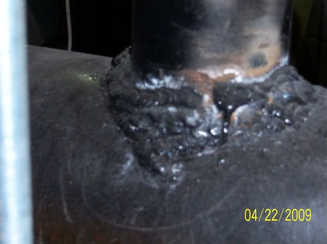
In addition to things that others have said, you should look at the "Weld Toe" condition at the top of the stiffeners. The slightest weld overlap and /or undercut defect at the wrap around weld on the top of the stiffener often results in failure through the thickness of the tube. This area is especially succeptable to weld defects such a lack of fusion at the root, slag inclusion, Undercut and Overlap, because it is in the stop/re-start area, and the weld is often very short.
The overlap condition is actually just a contributing factor, but the chevrons on the crack faces (on the pole and stub after the pole cracks and falls) point to the overlap spots like a road map. I feel that Undercut and Arc Strikes can more legitimately be blamed for the fatigue failures than the overlap.
I have seen many failures blamed on this "stiffener installation" repair solution and the associated welding, but I think it is a rather poor method of repair for what is really a fatigue condition design problem. When the next failure happens, the failure will be blamed on the badly made welds, and the sloppy engineering will be off the hook! That is good for the Engineer and the Manufacturer, but not so good for the welders and the inspectors!
If you are an independent operator type of CWI, watch yourself!!!! If you are an advisor to the owner of the pole, tell him that it is not a good idea to use his own welders for this type of work. Advise him to have the "manufacturers welders" perform the repair.
Quite a few, with most changing to a more stringent criteria.
It makes sence to me, with more challenging materials and constructions, better inspection techniques most be applyed.
There is a thread here about arc strikes on cross country pipelines, many moons ago the material used for such pipelines was of a lower steel grade, with lower Ceq. now the materials has a higher Ceq. and arc strikes becomes an issue.
3.2
Thank you all for those kind words but, I wouldn't be comprehensive in my description without mentioning the importance of covering up any piping or hangers or anything that could easily receive an arc strike if not covered up by either some refrasil/novatex, or some plain old EB Green, or any other type of duct tape in order to insure that the only thing that's going to receive a weld deposit without having any arc strikes surrounding it, is gonna be the location you're aiming the rod or tungsten at!!!
So don't forget to cover up and cover up real good!!! :) :) :)
Respectfully,
Henry
Yes, but even that piss poor of a weld held for at least 30 up to almost 60 years. It was not the weld that failed. It was the pipe.
But this shows how pipeline welding has evolved. I hope to someday turn up an old El Paso Nat Gas Weld where the arc strikes had to be on the pipe or the welder could get run off. No welder was going to weld on El Paso pipe with a cold welding rod. That thing better be red hot when you get in the bevel.
We laugh but the books, codes and standards we use today were written by these guys. I have hear stories about 400 joint days on 6 inch pipe.That would be 2 bead hands, 2 hot pass and 4 on the firing line. And the firing line better be within 2 set ups when the front end shut down. That is over 3 miles a day. If the bead hand put in too much bead, hot pass had to add and then the firing line had to strip before capping. Ass whoopins would happen. But this was all before xray.
Why do you think I quoted "During welding, the maximum temperature of the base metal shall not be greater than 600 degrees F"
I agree that the WPS is written for the welder, but it is also written for the engineer, inspector or whoever is assigned to review the WPS.
He needs information about preheat, interpass and filler selection amongst other things...PWHT comes to mind.
I am often on projects with high temperature materials, USC boilers.
Very often my client has restrictions on the things I mentioned above, not because he has stocks in the required filler material manufactor, but because he has tested this particular rod/wire.
Another thing is, as part of the welders qualifiation test, he should also be tested in his general knowledge, including how to read a wps!
Before any welder on a project where am the responsible inspector even strikes the arc on P91/92 or X20 he has passed a small test, including how to read a specific test.
If a welder cant read and follow a WPS, he should not be welding. I honestly think that it is a very fair requirement.
3.2
For what its worth not beingin a class with you gentlemen.Shane is correct about the disguising of arc strikes that happens i have been told personaly if it happens to file it and then smear loose grinding dust over the area as well as smearing dirt / mud to hide it. Also this was being done at a 6g certifcation test .Instructions i have recieved which i dont agree with, if the inspector doesnt see it be quiet about it ,we'll fix it later.
Jameson,
Sorry to say I agree with your QC manager on this one.
B31.3 seems to be quite clear to me "Tack welds shall be made by a qualified welder or welding operator."
There is no way inexperienced and/or unqualified welders should be putting in root tacks. It is impossible to get the preps back to the original
dimensions when you have to "knife" a tack out. It is even worse when they have put excess penetration in and you have to somehow cut through it and hook the "dag" out through the root gap.
Bridge tacks can be almost as bad. While they leave the prep untouched/undamaged, if someone is inexperienced they can put arc strikes all around the bullets which can be just as detrimental.
However, why do you not qualify your welders with an all positional fillet weld test if they are unable to achieve an open groove pipe welding qualification. That way you satisfy the code, your manager is happy and hopefully you can see the ability of your welders before they go attacking the pipes and installing bridge tacks.
Regards,
Shane
Letterburn
I have slide pictures of an arc burn that went clear through the weld on a 3/8 wall 16 inch gr 56 API 5LX gas pipe. I have several other slides of arc strikes and arc burns caused by poor connections.
I do not see how it could take too long to pull a bungee cord around the pipe. It takes ten times that long to get the welder to put his cigarette out!
In most of the projects where I have been the inspector, the NYS Public Service Commission is right behind me doing their own QA inspection. They are so strict that they made me reject punch marks that the fitter used for layout assembly, and treat them as arc strikes. (Grind out, polish and macro etch with Amonium Persulfate solution.) If you do not do a thorough inspection, they tell the owner to get rid of you.
Grind the tip to fit your needs and they work great - powder coat has to come off on the tip regardless, which is what we've done. The pieces are cnc cut - so some fitting is necessary. The tip is 3/8" thick - pics give kind of deceiving angles, hehe.... around 16" in overall length. Zip ties work great - fast and cheap - personally, I run the lead through the hairpin and keeps out of the way.
Also, hard to see it but the legs have angle into them - maybe the second pic you can see it, the one w/o the insulating hose - but when latched onto the pipe, it actually puts pressure on the tip. Bungess are too slow for pipeline ... once your juice flows through it - some of the swampers have been surprised how well it sticks to the weld / bevel.
Thank goodness I've not been on your jobs - however, in the past year that I've been using mine - my bare (uncoated) hopper - has never given me any arc burns / strikes - only occasionally a damn rod coming out of the groove of my stinger when I get lax (I mean.... I've never gotten any arc burns in my life, hehe). Oh yeah.... if you look at other pics too - I showed a set w/o the insulating heater hose - but you've got to put heater hose on legs - also there's a rubber snubber on each leg set to prevent bottoming against steel.
I've been pipelining w/ these - you shoulda seen my first grasshopper - about got laughed off the row and damn good thing it didn't land on my head, lol
DL
In my opinion, the cross sectional area at the contact tip is too small, and not in the correct shape. You would have lots of arc burning. You also need a few loops to anchor the tie down bungees needed to assure tight contact. There should be a wider transverse contact tip. In addition, there should be a flat bar end with a face angle complement to the 37 1/2 degree angle and a 90 degree face, so that when you are doing double ending, or fitting small components, you could lay the flat bar against the bevel face, and the arc strikes would get remelted during the welding.
If you used your gadget on the jobs where I was the inspector, it would be disallowed for excessive arc strikes/ arc burns. The PSC would have a fit!
Thanks for the follow thru with the pictures. It makes a very good point when questions arise about the seriousness of arc strikes. (As did some pictures a while back John posted of his test on coupons and a standard coupon bender- Thanks for those.)
I have used John's several times with welders after I have marked a strike for repair and they question the reason for repair. I will add this to my personal collection of stats.
Hope you would have eventually posted this even if you had deleted the original post when you ran into problems with the pics.
Have a Great Day, Brent
Thats good instruction Jim!
Those photos really bring home the importance of preventing arc strikes
Red dye doesn't lie.
Teacher jokes welcomed :)
Hey Jim. The pics are up. Do you know what the problem was? I tried to post pics yesterday and could not so I deleted my post. After all the smart a**** responses by this hostile crowd I wasn't about to go through that :)
On the subject of
arc strikes, the PT shows why they should be avoided. Especially with certain grade materials. Good lesson.
For a nominal fee I can provide instruction so your vendor can turn out welds like these.
[
http://i304.photobucket.com/albums/nn196/swsweld/008-1.jpg]
Check out these pictures from a project that we are involved in. You are seeing some vendor supplied piping. The vent piping you see in picture 002 shows an arc strike. Picture 001 shows a leak. Picture 004 shows excavation of leak area. Picture 005 shows propagation of crack shown by PT. This is P91 material. This is a text book example of why arc strikes need to be dealt with.
Jim
Stick= SMAW electrode
Wash= moderate to large weave
HMFIC= head mother F***er in charge
All slang terms for police = applied to Inspectors... Cop, Copper, pig, hudda, rosco etc...
Dingle berry= splatter
Quiver=SMAW electrode bag
weed burner= Propane torch usually only used for pre/post heat.
potato face=welder with flash burned eyes
Green, Green horn, or Rookie = anybody new to the trade
Fizzel= welding or carbon arc sparks
sizzel=Sound that GMAW makes when it is set properly
bubble gum=weld with lack of fussion &/or porosity/weld with lumps and bumps.
Zoro= welder trying to un-stick the SMAW electrode
Chicken scratch= arc strikes outside weld area.
walking papers / Bounced / snake eyes= getting fired or laid off.
wowie= any weld or material with at least one bend that is not suposed to be there.
And my personal favorite...
Lumber rod= very special SMAW electrode used to weld wood or pallets together (always send the green horn to the HMFIC to get some lumber rod and watch what happens - always a good laugh)
Thanks again for your help~
The defects in question were definitely no worse than weld profile produced by SMAW. The thing is, like I said, there were only about 5 places over a very large amount of welds that had this condition, and the defects did not have sharp transitions. When I visually inspect our welds I try to look for the normal discontinuities - piping porosity, undercut, excessive/lack of reinforcement, surface inclusions, lack of fusion, arc strikes on based metal, spatter, etc. But the smaller defects such as these will often go unnoticed until blasting occurs and the defects are more visible. We try to train our employees to spot defects during welding and blasting/painting, but still some things go unnoticed. I guess the lesson here is no company's welds are perfect, but the customer is always right, so if they see something they don't like and you can't negate it by code requirements then you bite the bullet and make the repairs.
Looks like there are a lot of other great articles regarding welding. Can anyone provide a link to, or please send me a copy of these articles?
Welding
Alternate acceptance criteria series:
principles and use July 92
weld profile Sept 92
porosity Nov 92
arc strikes Jan 93
undercut Mar 93
weld size May 93
craters July 93
incomplete fusion Sept 93
surface slag Nov 93
weld length Jan 94
overlap Mar 94
cracks May 94
Weld convexity limits - interpretation of AWS July 92
What's the minimum size fillet weld? Mar 93
Minimum weld size - a follow-up Sept 93
New weld termination provisions Nov 93, Mar 94
Welding Inspection and OSHA Jan 95
These would be great teaching aids.
As a new CWI you may feel you are being baffled by science by the responses here but I think you did the right thing. You just need to learn, with experience, how not to make this like this a show-stopper. In my opinion all you needed to do was ask for the arc strikes to be removed by grinding and do a quick visual, and if the material is higher strength and more supsceptible to cracking, insist on magnetic particle test to ensure that no cracks have formed. Do not worry you, will get there and I think you have the right attitude to start out with as an inspector, don't be bullied. Good luck.
NKG
These conditions are easily corrected by grinding. The deepest, nastiest arc strikes I have ever seen only penetrate about 1/8". Which goes to show they are still important to keep an eye out for them as they can be a crack initiator. However consider that 90% of precast connections are for lateral restraint and/or designed to be loaded in shear. The actual weight of the panels, beams, columns, T's, double T's, Triple T's, risers... is transfered via bearing pads and or grout (packed or flowable). Some connections, usually groove welded, are designed to transfer compressive or tensile loads, but that does not sound like your condition.
Additionally, MT is more than adequate to verify removal of the affected area. Unless you have a 5 to 10MHz transducer (and corresponding test procedure) you will not see an indication even if a crack has started.
bruce69,
One of my worst jobs was inspecting tilt-ups. I spent about 9 months in a prison that was under construction. After the first couple of months, when they had completed minimum security and shipped in inmates, they went to 90% inmate labor. There ended up being all kinds of problems with this.
As far as rejecting these connection plates due to arc strikes, be careful. Just as a warning. The code states that arc strikes should be avoided. There is no requirement for them to be repaired, just because they are arc strikes. What will necessitate a repair is when arc strike discontinuities are called cracks. By labeling them as such you may be required to prove your position. One of the difficulties in doing so is applying MT to an area that is not required to have MT performed, as this is the most common way to confirm a crack.
CYA brother! D1.1 I assume is what you're using?
D1.1:2008 5.29 "Arc strikes should be avoided... Cracks or blemishes caused by arc strikes SHALL be ground to a smoothe contour and checked to ensure soundness."
I would think another NDT method would need to be employed, maybe UT to check them out.
You got pictures?
That figure is one of the weldor tests you can give, just make sure its the one you really need. (I personally have not done a 3/8" test plate in over 10 years, a total waist of my time, do it with 1/2" or more. Side bends are easy, with less prep to do the bends)
The Short Version:
Start with table 4.10 find the joints your weldor is going to doing, then go to table 4.11 find your joint covering the most or all being used in production, (note the thickness) this table lists all the test parameters/ranges along with the figure that goes with each test. If you don't already have a WPS for testing, write one around the process, electrode manufactures recommendations, amp/volt range that works etc. etc. etc......................... Assuming you have access to the test equipment to finish the test you are giving you can now finish the test. Note Part C - 4.18.3 will take you to 4.8.1 for visual, and don't forget 4.22, this is the most missed part of a WQTR document, see sample Form N-4.
For Prequalified joints as used in production go to Clause 3, Clause 4 is for qualification testing of PQRs. WPSs. WQTRs only. (except table 4.5 is referred to in Clause 3.6)
I posted this the other day and it may be of help to you also. I listed the code references that go along with the requested information on the documentation. Its from the 04
Enjoy
Type of Weldor (D1.1.4.1.2)(Manual or Machine)
Variables (D1.14 Part C.4.7 & 4.21 & 4.22 Table 4.11)(D1.5.5.24)
Material / Specification (D1.1 Table 3.1)(D1.5.5.21.3) To
Base Metal (D1.1.3.3)(D1.1.1.2 - 100 ksi yield limit)(D1.5.5.24.1.1 - 90 ksi yield limit)(D1.5.1.2.2 & 5.4.3 base metals)
Plate Thickness: (D1.1 Table 4.10)(D1.5 Table 5.7)
Groove: (D1.1.3.7.2)(D1.1.4.23 & 4.30)(D1.5.5.23.1.2)
Fillet: (D1.1.3.7.2)(D1.1.4.25 & 4.30)(D1.5.5.23.1.3)
Pipe Diameter / Thickness: (D1.1 Table 4.10)
Groove: (D1.1.4.26 & 4.30)
Fillet: (D1.1.4.30)
Joint Type (D1.1.3.9, 3.10, 3.11, 3.12 & 3.13)(D1.1 Table 3.7 & Figures 3.2, 3.3, 3.4, 3.5, 3.6, 3.7, 3.8, 3.9, 3.10 &3.11)
Process / Type (D1.1.3.2.3)(D1.1.Table 4.11 #1)(D1.5.5.24.1.2)
Backing (D1.1.4.19.1.2)(D1.1.Table 4.11 #6)(D1.5.5.23.1.2 & 5.24)___________Size (D1.1.5.10.3)(D1.5.3.13.4) __________
Position (D1.1.4.23.1 Table 4.9)(D1.5.5.24.2.2)
Weld Progression (D1.1.3.7.1)(D1.5.4 .6.8)
Filler Metal (D1.1.3.3)(D1.1.Table 4.11-Item 3)(D1.1.5.3.2.2)(D1.5 Tables 4.1, 4.2 & 4.3)
Specification No. / Class (D1.1.Table 3.1)(B2.1 Table C1)
F Number (D1.1.Table 4.11-Item 2 & Table 4.12)(B2.1 Table C1)
Gas / Flux Type (D1.1.Table 4.11-Note 2)(D1.1.4.22)(D1.5 Table 5.3 #13)__________ Flow Rate _____________
Electrode (D1.1.5.3.4)(D1.1.5.3.2, 5.3.2.1)(D1.5.5.24.2.1)
Single / Multiple (D1.1 Table 3.7)(D1.1.Table 4.5 #11 & 4.11 #7)(D1.5.5.21.2)
Diameter / Manufacturer (D1.1 Table 3.7) (D1.1.5.3.3.1)(D1.1.Table 4.5 #10)(D1.5.5.21.2)
Welding Procedure Specification No. (D1.1 Table 3.7)(D1.1.5.5)(D1.5.5.21.2)(D1.1.3.6) Rev.
Preheat (D1.1.3.5)(D1.1.5.6 & 5.7)(D1.5.4.2) Maximum Interpass Temperature
Stringer or Weave (D1.1.Table 4.6 #11)(D1.5.5.12 & 5.13 & Table 5.3)(see KJ inch heat input)
Current / Polarity (D1.1.3.6 Table 3.7)(D1.5.21.2) Volts ___________Amps____________ + or -Polarity_______
Travel Speed________ Rod Temperature (D1.1.5.3.2.2) (D1.5.4.5) __________CVN _________ F° ________ lbs
Minimum required KJ inch (D1.1.Table 4.5 & 4.6)(D1.5.5.12, 5.13 Tables 5.3, 12.3, 12.4 & 12.5)
(Volts x Amps x .06 divided by Travel speed = KJ inch) or (Volts x Amps x .06 divided by KJ inch = Travel speed)
Weldor Test Information (D1.1 Annex E Form E-4)(D1.5 Annex III Form III-4)
Name _________ ID # _________
Type of Weldor (D1.1.4.1.2)__________ Date of Test ____________
Welding Procedure Specification No. (D1.1 Table 3.7)(D1.1.5.5)(D1.5.5.21.2)(D1.1.3.6) Rev.
Variables (D1.14 Part C.4.7 & 4.21 & 4.22 Table 4.11)(D1.5.5.24) Record actual values used in qualification test
Process / Type (D1.1.3.2.3)(D1.1.Table 4.11 #1)(D1.5.5.24.1.2)
Stringer or Weave (D1.1.Table 4.6 #11)(D1.5.5.12 & 5.13 & Table 5.3)
Current / Polarity (D1.1.3.6 Table 3.7)(D1.5.21.2) Volts_____ Amps_______ + or - polarity _______
Position (D1.1.4.23.1 Table 4.9)(D1.5.5.24.2.2)
Weld Progression (D1.1.3.7.1)(D1.5.4 .6.8)
Backing (D1.1.4.19.1.2)(D1.1.Table 4.11 #6)(D1.5.5.23.1.2 & 5.24) __________Size (D1.1.5.10.3)(D1.5.3.13.4)__________
Material / Specification (D1.1 Table 3.1)(D1.5.5.21.3)__________To____________Heat #_____________
Joint Type (D1.1.3.9, 3.10, 3.11, 3.12 & 3.13)(D1.1 Table 3.7 & Figures 3.2, 3.3, 3.4, 3.5, 3.6, 3.7, 3.8, 3.9, 3.10 &3.11)
Electrode (D1.1.5.3.4)(D1.1.5.3.2, 5.3.2.1)(D1.5.5.24.2.1)
Single / Multiple (D1.1 Table 3.7)(D1.1.Table 4.5 #11 & 4.11 #7)(D1.5.5.21.2)
Diameter / Manufacturer (D1.1 Table 3.7)(D1.1.Table 4.5 #10)(D1.5.5.21.2)
Filler Metal (D1.1.3.3)(D1.1.3.3)(D1.1.Table 4.11-Item 3)(D1.1.5.3.2.2)(D1.5 Tables 4.1, 4.2 & 4.3)
Specification No. / Class (D1.1.Table 3.1)(B2.1 Table C1)
F Number (D1.1.Table 4.11-Item 2 & Table 4.12)(B2.1 Table C1)
Gas / Flux Type (D1.1.Table 4.11-Note 2)(D1.1.4.22)(D1.5 Table 5.3 #13)_________ Flow Rate_________
Base Metal (D1.1.3.3)(D1.1.1.2 - 100 ksi yield limit)(D1.5.5.24.1.1 - 90 ksi yield limit)(D1.5.1.2.2 & 5.4.3 base metals)
Plate Thickness: (D1.1 Table 4.10)(D1.5 Table 5.7)
Groove: (D1.1.3.7.2)(D1.1.4.23 & 4.30)(D1.5.5.23.1.2)
Fillet: (D1.1.3.7.2)(D1.1.4.25 & 4.30)(D1.5.5.23.1.3)
Pipe Diameter / Thickness: (D1.1 Table 4.10)
Groove: (D1.1.4.26 & 4.30)
Fillet: (D1.1.4.30)
Rod Temperature (D1.1.5.3.2.2) (D1.5.4.5)_________Wind (D1.1.5.12.1)(D1.5.4.14.3)________
Preheat (D1.1.3.5)(D1.1.5.6 & 5.7)(D1.5.4.2)_______ Maximum Interpass Temperature________
Ambient Temperature (D1.1.5.12.2)(D1.5.4.2)_______Weld Length______ Travel Speed__________
Minimum required KJ inch (D1.1.Table 4.5 & 4.6)(D1.5.5.12, 5.13 Tables 5.3, 12.3, 12.4 & 12.5)
(Volts x Amps x .06 divided by Travel speed = KJ inch) or (Volts x Amps x .06 divided by KJ inch = Travel speed)
Appearance of welds (D1.1.4.8.1)(D1.5.6.26)(D1.5.5.21.5)(D1.5.6.4.4 Inspector observation required)
Root pass (D1.1.4.8.1-4&5)(D1.1 Table 6.1)(D1.5.6.26.1.2)(D1.5.5.21.5)
Intermediate passes (D1.1 Table 6.1)(D1.1.5.30)(D1.5.6.26.1.2)(D1.5.3.11)(D1.5.5.21.5)
Cover pass (D1.1.4.8.1)(D1.1 Table 6.1)(D1.1.5.24, 5.27 & 5.28)(D1.5.3.6, 3.8 & 3.9)(D1.5.6.26)
Undercut (D1.1.4.8.1)(D1.5.5.27.1)
Porosity (D1.1 Table 6.1)(D1.5.5.27.4.1)(D1.5.6.26.1.6)
Arc Strikes (D1.1.5.29)(D1.5.3.10)
Name of Welding Test Witness (D1.5.6.4.4 Inspector observation required)
(I would quote paragraph 5.29 from D1.1, but mpitt already has done that)
"D1.1 states "Cracks or blemishes cause by arc strikes shall be ground to a smooth contour and checked to ensure soundness."-quote
AWS D1.1:2008 paragraph C-5.29 Arc strikes result in heating and very rapid cooling. When located outside of the intended weld area, they may result in hardening or localized cracking, and may serve as potential sites for initiating fracture.
I think these bend tests prove this out...now as an inspector, is it up to me to now prove that this material is sound and safe for use in the structure as is with these arc strikes / drag marks?....I don't think so, therefore when I see it, it gets addressed. I don't want or need the added responsibility of proving that the material is OK "as is" or not.
On the AISC websites Engineering FAQ's they say that "In Statically loaded structures arc strikes need not be removed, unless such removal is required in the contract documents" but for "Cyclically loaded structures arc strikes may result in stress concentrations that would be detrimental to the serviceablility of such structures and should be ground smooth and visually inspected for cracks."
D1.1 states "Cracks or blemishes cause by arc strikes shall be ground to a smooth contour and checked to ensure soundness."
If the job specs say all welding to be done per AWS D1.1,since D1.1 is mentioned in the job specs, all arc strikes have to be removed and inspected. It does not state if it is to be done visually or some other NDE method.
API 1104 A.5.3 gives accepttable limits for unrepired arc burns. It also states "Arc burns that contain cracks visible to the eye or on conventional radiographs are not covered by this appendix and shall be repaired or removed."
I laid the 4 pieces of flat bar on a welder's table, I explained that this was an experiement that I wanted to try and asked him to quickly drag an E7018 across to simulate an arc strike. He made one quick swipe with the rod. Then I asked him if that happened, how would he repair it, he said he would grind it out. So I asked him to show me...he grabbed the grinder and proceeded to grind out where he saw the arc strikes. I then asked him if he thought it would be OK now, and he agreed that he thought it should be OK now. So I took those pieces and turned the ground side away from the plunger so the material would stretch across the arc strikes and bent them. I asked him to watch me perform the bending, so he would know that I didn't do anything to them to make them tear.
Not really....that would be a good idea to see just how deep the arc strikes have an effect on the parent material....this may be dependant on the arc strike and the amount of time the electrode was in accidental contact though.
don't get me wrong, arc strikes are bad. I try not to make them, but it does happen. the best thing you can do is try not to make them, and if you do document the arc strike, see what the inspector want to do or the client, and go on with whatever is wanted or needed. control what you can control and don't sweat the small stuff. Yes I DID recomend 309L for carbon steel porosity when all else fails.
Could somebody point out the location of the rejection criteria for arc strikes under ASME B31.1, B31.3, and ASME Section I?
thank you
scrappywelds,
I have worked with boilers many times in the past. With recovery boiler specifically, I have seen arc strikes that have caused catastrophic failures. No offense and nothing personal, but welders and inspectors have different experiences. I'm sure you have seen 50 year old arc strikes that had no influence on the integrity on the unit, I have as well. As an inspector we are called out when there is a failure. So the things you feel are old wives tales really do happen, maybe you have just not been involved. I have seen super heater loops that split at arc strikes, resulting in unbelievable damage. Tube walls that have blown out due to arc strike.
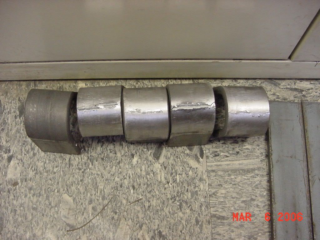
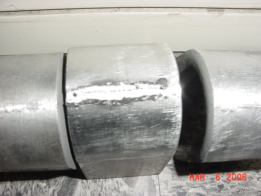
Since others have mentioned my pictures, I'll post them again.
I had a welder lay 5 pieces of 2" wide, 3/8" thick, flat flatbar side by side and then had him drag a E7018 quickly across 4 of these pieces. Then I had him grind lightly on these pieces until he could no longer see his
arc strikes. Once he was satisfied that he had fixed his
arc strikes, then I bent all 5 of them in my coupon bender for A36 material(including the one without
arc strikes).
A36 flat bar with
arc strikes, ground out to the welder's saticfaction and then bent in a coupon bender.
[
http://img.photobucket.com/albums/v345/jwright650/welding%20pictures/arcstrike2.jpg]
close up
[
http://img.photobucket.com/albums/v345/jwright650/welding%20pictures/arcstrike4.jpg]
I still have these pieces to use as discussion points with my new welders who are in training.
also someone mentioned that they attended a engineers conference and that the result of the conference was that there has never been a catastrophic failure of something or other (cant remember this part), but the protocol was to continue to treat arc strikes like a critical deficiency.
bend them to code determine if they pass then bend em till they stretch and malform for your own knowledge is the way i like to treat my own coupons.... or my competitors....cause its welders competitive nature that makes us better and why a lot of us enjoy the job.
darren
This may be of help. I made this as part of a lecture many years ago using the D1.1 and D1.5 as its basis
I had listed the code references that go along with the requested information on the documentation.
Enjoy
Type of Weldor (D1.1.4.1.2)(Manual or Machine)
Variables (D1.14 Part C.4.7 & 4.21 & 4.22 Table 4.11)(D1.5.5.24)
Material / Specification (D1.1 Table 3.1)(D1.5.5.21.3) To
Base Metal (D1.1.3.3)(D1.1.1.2 - 100 ksi yield limit)(D1.5.5.24.1.1 - 90 ksi yield limit)(D1.5.1.2.2 & 5.4.3 base metals)
Plate Thickness: (D1.1 Table 4.10)(D1.5 Table 5.7)
Groove: (D1.1.3.7.2)(D1.1.4.23 & 4.30)(D1.5.5.23.1.2)
Fillet: (D1.1.3.7.2)(D1.1.4.25 & 4.30)(D1.5.5.23.1.3)
Pipe Diameter / Thickness: (D1.1 Table 4.10)
Groove: (D1.1.4.26 & 4.30)
Fillet: (D1.1.4.30)
Joint Type (D1.1.3.9, 3.10, 3.11, 3.12 & 3.13)(D1.1 Table 3.7 & Figures 3.2, 3.3, 3.4, 3.5, 3.6, 3.7, 3.8, 3.9, 3.10 &3.11)
Process / Type (D1.1.3.2.3)(D1.1.Table 4.11 #1)(D1.5.5.24.1.2)
Backing (D1.1.4.19.1.2)(D1.1.Table 4.11 #6)(D1.5.5.23.1.2 & 5.24)___________Size (D1.1.5.10.3)(D1.5.3.13.4) __________
Position (D1.1.4.23.1 Table 4.9)(D1.5.5.24.2.2)
Weld Progression (D1.1.3.7.1)(D1.5.4 .6.8)
Filler Metal (D1.1.3.3)(D1.1.Table 4.11-Item 3)(D1.1.5.3.2.2)(D1.5 Tables 4.1, 4.2 & 4.3)
Specification No. / Class (D1.1.Table 3.1)(B2.1 Table C1)
F Number (D1.1.Table 4.11-Item 2 & Table 4.12)(B2.1 Table C1)
Gas / Flux Type (D1.1.Table 4.11-Note 2)(D1.1.4.22)(D1.5 Table 5.3 #13)__________ Flow Rate _____________
Electrode (D1.1.5.3.4)(D1.1.5.3.2, 5.3.2.1)(D1.5.5.24.2.1)
Single / Multiple (D1.1 Table 3.7)(D1.1.Table 4.5 #11 & 4.11 #7)(D1.5.5.21.2)
Diameter / Manufacturer (D1.1 Table 3.7) (D1.1.5.3.3.1)(D1.1.Table 4.5 #10)(D1.5.5.21.2)
Welding Procedure Specification No. (D1.1 Table 3.7)(D1.1.5.5)(D1.5.5.21.2)(D1.1.3.6) Rev.
Preheat (D1.1.3.5)(D1.1.5.6 & 5.7)(D1.5.4.2) Maximum Interpass Temperature
Stringer or Weave (D1.1.Table 4.6 #11)(D1.5.5.12 & 5.13 & Table 5.3)(see KJ inch heat input)
Current / Polarity (D1.1.3.6 Table 3.7)(D1.5.21.2) Volts ___________Amps____________ + or -Polarity_______
Travel Speed________ Rod Temperature (D1.1.5.3.2.2) (D1.5.4.5) __________CVN _________ F° ________ lbs
Minimum required KJ inch (D1.1.Table 4.5 & 4.6)(D1.5.5.12, 5.13 Tables 5.3, 12.3, 12.4 & 12.5)
(Volts x Amps x .06 divided by Travel speed = KJ inch) or (Volts x Amps x .06 divided by KJ inch = Travel speed)
Weldor Test Information (D1.1 Annex E Form E-4)(D1.5 Annex III Form III-4)
Name _________ ID # _________
Type of Weldor (D1.1.4.1.2)__________ Date of Test ____________
Welding Procedure Specification No. (D1.1 Table 3.7)(D1.1.5.5)(D1.5.5.21.2)(D1.1.3.6) Rev.
Variables (D1.14 Part C.4.7 & 4.21 & 4.22 Table 4.11)(D1.5.5.24) Record actual values used in qualification test
Process / Type (D1.1.3.2.3)(D1.1.Table 4.11 #1)(D1.5.5.24.1.2)
Stringer or Weave (D1.1.Table 4.6 #11)(D1.5.5.12 & 5.13 & Table 5.3)
Current / Polarity (D1.1.3.6 Table 3.7)(D1.5.21.2) Volts_____ Amps_______ + or - polarity _______
Position (D1.1.4.23.1 Table 4.9)(D1.5.5.24.2.2)
Weld Progression (D1.1.3.7.1)(D1.5.4 .6.8)
Backing (D1.1.4.19.1.2)(D1.1.Table 4.11 #6)(D1.5.5.23.1.2 & 5.24) __________Size (D1.1.5.10.3)(D1.5.3.13.4)__________
Material / Specification (D1.1 Table 3.1)(D1.5.5.21.3)__________To____________Heat #_____________
Joint Type (D1.1.3.9, 3.10, 3.11, 3.12 & 3.13)(D1.1 Table 3.7 & Figures 3.2, 3.3, 3.4, 3.5, 3.6, 3.7, 3.8, 3.9, 3.10 &3.11)
Electrode (D1.1.5.3.4)(D1.1.5.3.2, 5.3.2.1)(D1.5.5.24.2.1)
Single / Multiple (D1.1 Table 3.7)(D1.1.Table 4.5 #11 & 4.11 #7)(D1.5.5.21.2)
Diameter / Manufacturer (D1.1 Table 3.7)(D1.1.Table 4.5 #10)(D1.5.5.21.2)
Filler Metal (D1.1.3.3)(D1.1.3.3)(D1.1.Table 4.11-Item 3)(D1.1.5.3.2.2)(D1.5 Tables 4.1, 4.2 & 4.3)
Specification No. / Class (D1.1.Table 3.1)(B2.1 Table C1)
F Number (D1.1.Table 4.11-Item 2 & Table 4.12)(B2.1 Table C1)
Gas / Flux Type (D1.1.Table 4.11-Note 2)(D1.1.4.22)(D1.5 Table 5.3 #13)_________ Flow Rate_________
Base Metal (D1.1.3.3)(D1.1.1.2 - 100 ksi yield limit)(D1.5.5.24.1.1 - 90 ksi yield limit)(D1.5.1.2.2 & 5.4.3 base metals)
Plate Thickness: (D1.1 Table 4.10)(D1.5 Table 5.7)
Groove: (D1.1.3.7.2)(D1.1.4.23 & 4.30)(D1.5.5.23.1.2)
Fillet: (D1.1.3.7.2)(D1.1.4.25 & 4.30)(D1.5.5.23.1.3)
Pipe Diameter / Thickness: (D1.1 Table 4.10)
Groove: (D1.1.4.26 & 4.30)
Fillet: (D1.1.4.30)
Rod Temperature (D1.1.5.3.2.2) (D1.5.4.5)_________Wind (D1.1.5.12.1)(D1.5.4.14.3)________
Preheat (D1.1.3.5)(D1.1.5.6 & 5.7)(D1.5.4.2)_______ Maximum Interpass Temperature________
Ambient Temperature (D1.1.5.12.2)(D1.5.4.2)_______Weld Length______ Travel Speed__________
Minimum required KJ inch (D1.1.Table 4.5 & 4.6)(D1.5.5.12, 5.13 Tables 5.3, 12.3, 12.4 & 12.5)
(Volts x Amps x .06 divided by Travel speed = KJ inch) or (Volts x Amps x .06 divided by KJ inch = Travel speed)
Appearance of welds (D1.1.4.8.1)(D1.5.6.26)(D1.5.5.21.5)(D1.5.6.4.4 Inspector observation required)
Root pass (D1.1.4.8.1-4&5)(D1.1 Table 6.1)(D1.5.6.26.1.2)(D1.5.5.21.5)
Intermediate passes (D1.1 Table 6.1)(D1.1.5.30)(D1.5.6.26.1.2)(D1.5.3.11)(D1.5.5.21.5)
Cover pass (D1.1.4.8.1)(D1.1 Table 6.1)(D1.1.5.24, 5.27 & 5.28)(D1.5.3.6, 3.8 & 3.9)(D1.5.6.26)
Undercut (D1.1.4.8.1)(D1.5.5.27.1)
Porosity (D1.1 Table 6.1)(D1.5.5.27.4.1)(D1.5.6.26.1.6)
Arc Strikes (D1.1.5.29)(D1.5.3.10)
Name of Welding Test Witness (D1.5.6.4.4 Inspector observation required)
I believe our good friend John Wright was the fellow that told us of the experiment he uses to show the deleterious effects of an arc strike.
Drag the electrode across a piece of 3/8 x 1 1/2 carbon steel bar and subject the area with arc strikes to a bend test.
Most of us are used to using a bend fixture to ASME and AWS requirements. Those that are using a bending fixture to API 1104 requirements may not see the same results. The bend diameter for API is more generous than either ASME or AWS. I believe API 1104 is 1 3/4 inch radius where as AWS/ASME is 3/4 inch radius. A very important difference if you have ever considered using a welder qualified to API on an AWS or ASME project. You might want to check my figures, they're based on my fragile memory and that ain't saying much!
Happy Valentine's Day!
Best regards - Al
there was a good thread on it and i cant remember who but someone posted some bent coupons with only arc strikes on the and they all bust.
I agree with you lawrence, safety glasses are considered proper protection from welding radiation. Also unless your actively welding most people don't keep their AD hood down because it's kinda stiffly and still hard to see what your doing. I also agree that a auto darkening hood won't really improve safety besides maybe neck strain (also most of the new auto darkening hoods are lighter).
I suspect in this case the safety officer is demanding them? and if the company is willing to pay, I'm curious as to what the reluctance is from a welder to use the hoods.
Also I really do suspect it would marginally increase production time and help reduce things like arc strikes and tie ins, because you can accurately position the torch prior to striking an arc.
Elijah, I'd like to step in on this letting the arc go out. First and foremost, this lag time is not conducive to production. Period. In the construction field, it takes forever to deliver the parts, get a crane, rig it up, fit the piece. But hey, when it comes to the welding...oh my!, it's gotta get done NOW! And...We welders tend to be highly motivated when it comes to getting it done fast and burning more rod and often our jobs are on the line cuz time is money.
It is one of those gap filling and other "special use" tricks / applications handy to use when things get too hot.
As Allan metioned, the cellulose fluxed rods are highly dependant upon the sheilding gasses.
A theory of mine is that the intense heat and continuous/nonstop welding that is so typical of pipeliners (where 6010 type rods are used for the entire weld) helps cook out the hydrogen. To demonstrate, try these two experiments. Make two arc strikes on opposite sides (180 apart) on a piece of pipe, one with 6010 and the other with 7018. Let cool, brush off any slag and then file them down slowly. I think you will notice how much "softer" the 7018 is compared to the 6010. Now, tack down 2 pieces of plate (the same size of course to be acurate for our test) with 1/4" long tacks, onto another with each type rod, let cool. then break them off (tapping lightly with a small hammer like you were adjusting the fit) and notice how brittle the 6010 is over the lo-hi. Nothing scientific, just my own experience from fitting for welders (on structural shapes) who always want to tack with 5p (usually not to code) and then it breaks off if you need to tweak it into place (I don't let them, if they argue, i just tell them "you are a fusion machine and I'll pull you out of the tool box to use when and as I see fit! Then fill out the hurt feelings report!)
When ever we are learning anything new, speed increases with experience and familiarity. I think, you are just not quick enough on the draw yet and need that extra time (by breaking arc) to be more accurate to produce that stack of dimes/fishscale. As your coordination and visual acuity increases so too will that bead appearance.
It is just like learning a musical instrument, practice what seems like forever with no improvement and then suddenly it all comes together and you're playing Stairway to Heaven just like Jimmy Page!
Hang in there, it will all come together!
John
Hello spots, there are a number of things which could possibly give the indications that you are seeing as you have described them. First off, are you certain of the grain of the test pieces? If the grain is running the same direction as the weld joint you may see some "cracking" and in some cases you might even find some serious fractures. As you mentioned additionally, the grinding lines/marks, if they are ground with the marks in the same direction as the weld joint you could see additional possible indications/fractures. If the test pieces are being made from plate and the direction of rolling isn't apparent/known you could very well have issues come from this that aren't the fault of the tester. If you are using flat bar, even if it is correctly oriented it may exhibit some of this surface tearing due to the manufacturing process, in some cases, due to the size of the bar it will be subjected to a more rapid cooling rate than plate would be and this can have an effect on how it might bend or it's level of brittleness (a possible contributor to surface cracks).
There are some of the folks on the forum that have done some testing concerning arc strikes and such and have polished up bars with arc strikes on them and shown the effects of these problems regarding tearing (if you have seen arc strikes outside of weld zone, these would very likely show up as discontinuities and would justify a break-out), there have been others that have bent pieces with the grain going the wrong direction, I have bent pieces that I have ground the wrong way and found issues, I have also scribed lines across pieces and found issues with cracking related to that practice and many of these pieces didn't even have a weld in them they were simply a piece of flat bar of the same size as a test piece. I would leave you with one final thought, consider that cracks outside the area of the weld deposit are typically not an indication of the welders level of electrode application and manipulation skills. If there are cracks that are there due to excessive heat/incorrect prep and such then these might be due to not following the WPS that has been provided, this might lead you to question their skills with following this document and might justify a break-out. Personally, I tend to disregard indications outside of the actual weld zone as long as I can determine that they aren't related to the fusion line between the weld metal and the parent metal or have anything to do with an arc strike. Even though you are using A36 material, I wouldn't allow or get used to doing any rapid cooling of the test pieces, in other words I wouldn't dunk them in water. Technically speaking this shouldn't effect the test pieces due to their relatively low carbon content, yet, I believe you will find this to not always be the case. In D1.1 I believe there is a statement that speaks to cracks that don't exhibit any slag or lack of fusion and allows an additional coupon to be taken. So depending on your interpretation of this you might take this into consideration as well. I believe you will be receiving additional comments on this topic so stay tuned and make your best call after you have considered all of them. My $.02 Best regards, Allan
So I sholdn't get any wider than 1/2. Is this per API or ASME? Or a shop standard?
Intersting that you both are saying that you freehand the root and don't cup walk. It seems easier and more consistent to cup walk for me. I think it would be more difficult to cup walk the fill and cap passes.
Another question is that I am so used to using a remote to controll amperage that I can't seem to scratch start without getting a ton of arc strikes in the groove. Also it is difficult to have a short tungsten stickout to scratch start and then have too much electrode that I will dip my tungsten in the puddle or I will have a large torch angle.
What's with the arc strikes? ;0
Best regards - Al
I don't "think" that the electricity usage for a gouging electrode is any different than a simlarly rated welding electrode. I have hear the "wives tale" for many years and like so many of the posts have never seen any evidence supporting the claim.
I watched a powcon 300ST dead grounded and left overnight and came in the next morning to weld with it. That thing screamed all night long but was fine the next day.
I have often thought the constant UP/DOWN could be an issue but I would think that would be more on engine drives and also if that were the case then I would have to guess that a machine is mimited to a number of arc strikes.
poorly maintained machines with bat connections, improperly working coolong fans etc could also be subject to damage from high current loads however I don't see where the machine knows the difference.
The common misconception I see is that to gouge you max out the machine. That could allow one to exceed the duty cycle as sometimes the rated duty cycle of the machine is well below t he max current output.
Just thought I'd throw in my opinion.
:)
Usually arc strikes are in the area around the weld, which will be subject to PWHT anyway....
But, yes I agree, the client is the man......its his freaking pipes :)
Have a nice christmas
3.2
Every inhomogeneity associated with a weldment is a stress riser. Welds themselves are stress risers, especially at the toes. Porosity is a stress riser. Undercut is a stress riser. Slag inclusions are stress risers. Insufficient penetration is a stress riser. Thickness transitions are stress risers. Phase changes are stress risers.
And I do believe that more failures have been associated with thickness transitions, undercut, high entry angle weld toes, and phase changes, than arc strikes. This may be why, though I certainly don't know for sure, most of the ASME codes don't address the problem specifically. Though they do address more often thickness transitions through envelope maximums, and undercut (especially for fatigue regimes).
Not saying that arc strikes are OK, but my line of thinking may explain (IMO) some of the reticence in the codes, and my thought that we may be practicing a little bit too much handrwringing on this issue.
Firstpass, There was an article written not long ago I don't recall if it was in the "Journal" or the "Trends" which went went into great depth from all aspects of just how harmful the metal that is left behind from an arc strike actually is. "When I find it I will let you know" With that knowledge tactfully passed along I don't think you will have any trouble getting that ugly habit stopped. Besides when ever someone has left several arc strikes it clearly shows a lack of quality craftsmanship. And everyone will have one every once and a while. And if it's P-91 you just brought yourself a PWHT.
Whip
Arc strikes outside of the finished weld act as stress risers [crack-starters]. D1.1 2006 p202 5.29 states that they >shall< be ground to a smooth contour and checked to ensure soundness. Depending on the application [structural,transverse or parralel stress] and code applied they may or may not be an issue
Hi First pass,
I think you will find that the 3 inspection classes in B31.3 are Normal, Cat M / Severe Cyclic / Cat D.
There is quite a bit of information in the search engine, just type in "Arc Strikes".
I think it is the general consensus of the forum that the issue of arc strikes is not dealt with by the majority of the codes but are generally not allowed based on project specifications,
Regards,
Shane
para: 344.7 in process:
(g) appearance of the finished joint
This is the closest your going to come to it in the 06 code, and it's a wild card stretch of imagination inspectors should stay away from. It is left up to engineering and contract docs to define what and to what extent to be done with arc strikes.
A blanket statement will not typically work, as B31.3 covers hardenable and non-hardenable material, as well as other considerations.
31.3 has three different divisions of inspection normal, CAt M and CAT D.
arc strikes. They are a defect that can cause failure where does the code address them.
The Miller Trailblazers have 2 cylinder fully pressurized oil systems. They have a three phase welding arc. Very smooth easy arc strikes & restrikes. Can't say the same for the Rangers. They have single phase welding arcs.
Powered by mwForum 2.29.2 © 1999-2013 Markus Wichitill
