Not logged inAmerican Welding Society Forum
Forum AWS Website Help Search Login
Up Topic Welding Industry / Technical Discussions / Vertex angel (GTAW) less or more give good penetration
1 2 Previous Next  
Parent - By ssbn727 (*****) Date 09-29-2014 19:58
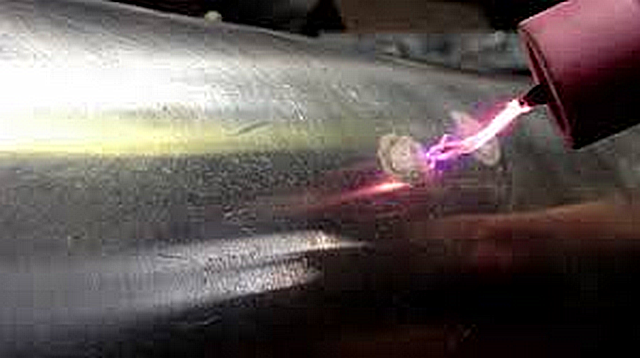
Okay so nobody really knows what's the reason for the photo being taken... Nobody here knows for sure the intent nor what actually occurred prior to, during, and/or after the HF plasma ignited as shown in the image Lawrence posted including Larry...:surprised::eek::lol::yell::lol::wink::cool: Although I do tend to lean towards Larry's explanation of what could have and/or what possibly did happen, and why as well including the intent/purpose of capturing the snapshot of the image in question and yet it's still only a very good probable explanation... Hmmmmm... Fascinating!

Well then I stand corrected for claiming that it was done intentionally by Lawrence for the purpose I previously posted, and I now understand the reason as being a mystery still... I do still stand by my answer for the last question posed by Plasma 56 regarding whether or not the tip was ground to a point and not blunted... The tip may look like there's a point that's been ground to a very tiny blunted end... However IMHO, the cause of that appearing to be a blunted tip showing in Larry's image is the intensely bright HF plasma itself "masking" the actual point of the electrode instead of it having a blunted tip... The wide coverage of those "spider legs" if you will are the result of the increased distance of the electrode from the base metal or metal table they're jumping onto, and if the distance is considerably shorter the ends of the thin streams of HF plasma are not anywhere near as widespread as what the image depicts...

All in all Lawrence... Your summary regarding the issues with manual GTAW is correct, comprehensive and well written...

As far as the pointed vs blunted tip is concerned, I totally agree with what you pointed out because of my own experiences with welding on very thin gauge 304L & 316L SS  both manually when tacking joints together, and also on mechanized GTAW with a Jetline seamer (Longitudinal seam welder with ALC as Jetline calls it which is arc length control which is basically the same as AVC:roll:), and welding the shells to the heads with an automated circumferential welding system I designed from different brand name components which I initially objected to and yet, still made it work to as close to perfection as possible...

The system also had a Cyclomatic AVC and a laser optical seam tracker on each welding head (2 to simultaneously weld both heads to the cylinder) to keep the arc from wandering off the seam of a square groove butt joint configuration especially when welding over the GTA spot welds that were used to tack weld the joint together... That blunted tip really did make a difference in controlling the bead profiles compared to using a pointed tip as I recall as well... I was thinking of incorporating a magnetic arc controller but it turned out that we didn't need it since our penetration and bead profile was just where we wanted it to be repeatably many moons ago...

I also remember the employer for whom I worked for when I designed the system and was let go from to put the owner's brother in law to replace me, called me up one day and asked me to come over on a Saturday to see if I could troubleshoot what was wrong with the system... I asked them if they couldn't find anyone else that could do this, and Ken answered "No because the few that did check it out all told me that I would have to ask the designer of the system to come and fix it for me!" I replied that I was going to charge him double my going rate, and if he wanted me to come up with a comprehensive manual for future reference he would have to pay for that also... Well, I fixed it in about 12 minutes and then put together a manual for them to have around in case something else happened to cause the system not to run properly and made $300 clams out of it which back in the late Eighties was some decent cash for about an hour and a half of  what you might call billable work.:roll::grin::lol::yell::twisted::yell::lol::yell::twisted::lol::wink::cool:

Respectfully,
Henry
Parent - By lo-hi (**) Date 09-30-2014 00:07
Lawrence, the high freq does dance and could stretch for inch's on some of the older point machines. And was great fun to surprise some of the new hires by giving them a blast. But if they did it  to there buddy sitting on a grounded bench, it starts a conflict. Perley
Parent - - By electrode (***) Date 09-30-2014 09:08
Lawrence,
thank you for confirming my presumption that your image was showing High Frequency spark(s) actually.
'lo-hi', saying: "And was great fun to surprise some of the new hires by giving them a blast. But if they did it  to there buddy sitting on a grounded bench, it starts a conflict." btw seems to confirm my assumption that human senses might be shook if making "a connection".

Apart from that... images, drawings and pictures.
Anyway, although a picture is known worth a thousand words.
To me it's worthless without adequate explanation as when it comes to non-trivial technical questions.
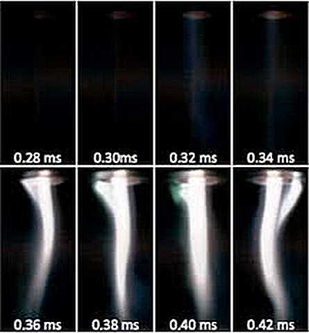
E.g. having a look at Henry's last post it was said that there are "4 various shaped plasma streams based on time exposure in milliseconds...".
I whereas interpret this as 8 images (in low resolution) supposedly showing the establishment of 1 (discharge) channel.
Presumably one of the reasons for e.g. OGAWA, deploying more advanced means such as streak imaging; more intricate to interpret, however.
You see my point? The more complicated the question the higher the risk to choose 'qualitative' instead of 'quatitative' tools thereby ending up in a "tit for tat exchange".
Definitely no disrespect intended here. I seem to understand why all these photographs and, with all due respect, partly confusing drawings (from a certainly bright Japanese fellow researcher) are used. They are, as they need to be, part of an open-minded discussion.
However, all this is not a trivial question and I'm afraid that brings Toey - whose original post I personally gratefully acknowledge because it keeps me learning - nowhere.

I suppose it needs more. The reason for me to say - I much appreciate Plasma56's experimental approach.
To gain real understanding it needs real effort. Plasma56 has practically tried to prove what he had suggested.
There must be a reason for "higher" penetration with lower acute angle tips.
He was saying: "That current density across the arc is affected by this profile change."
Not bad in my opinion, since that might point to somewhere.
But... 'why' and 'where'?

Any ideas?
Parent - - By Lawrence (*****) Date 09-30-2014 11:49 Edited 09-30-2014 12:22
I think the conversation is flittering around like hummingbirds in a flowerbed..  Lot's of assumptions.

I saw a penetration profile comparison of a pointed tip vs. a rounded tip... Saying the pointy tip would produce more penetration..  My "guess" here is that the rounded tip also represented an electrode carrying alternating current whilst the pointy tip represented DC- current...  Again.. All assumptions.... If my assumptions are accurate... I agree with the profiles illustrated.  But the profiles are more heavily driven by the current rather than the tip prep :)    (I think Henry alluded to this in a post)  And that's another entire conversation in itself.

There were also images of various tip preps for DC- and the resulting penetration profiles...

1)   The slim pointy tip producing a more bell shaped arc which makes a wider and more shallow penetration profile.

2)  The more radical tip prep producing a more conical arc and deeper penetration with a less wide profile

I agree with 1 & 2 as far as DC- applications... Those macros are repeatable for anybody willing to do an arc spot test.

Both 1 & 2 profiles (and many profiles in between) have practical uses for different desired effects with the welding arc.

One scenario
If I were building up an edge on thin sheet and needed a very accurate, low current arc start and did not want to burn away the base metal I would choose profile #1 (long, slim & pointy)  This will make a soft arc strike and a wide bell shaped arc that will be much more easy to work with.  

If I were making a fillet with the same thin gage base metal I would choose profile #2 to get the conical arc pointed at the root of the joint.  The bell shaped arc of #1 will "spread" the arc out and make root fusion difficult and increase the chances of undercut.  The bell shaped arc tends to "bridge" the root on thin materials at low current values.

Now,  to say that arc shape (bell vs cone) is the same thing as current density is an assumption that is above my professional paygrade...  I'm just not sure if the terms are technically accurate... But I think Plasma has proven in real-time what I've observed myself and seen in text...   The long slim pointy taper will cause a bell shaped arc and minimize penetration when compared to other tip preps.

I'm not sure if I'm even speaking to the original question.... But I hope this adds to the practical side of the conversation.

Edit:
I think Plasma also stated something key earlier that should be repeated/summarized for TIG welders:
It is sometimes counterintuitive, and many very experienced professionals have it exactly backwards....  The longer and slimmer taper does NOT produce greater penetration.

We could also discuss how AC frequency, balance, Asymmetric output and tip shape, changes the shape of a GTAW arc... But that would add confusion to this conversation.   :)
Parent - By electrode (***) Date 09-30-2014 14:05
Lawrence,

nicely summarised and tying the loose ends again.
Also, you are leading us all back to the OP's question, saying: "The longer and slimmer taper does NOT produce greater penetration."
It will be interesting to learn on other explanations for this "greater penetration".
Thank you.
Parent - - By electrode (***) Date 10-04-2014 17:59
Good.

Usure whether the OP has already closed this case.
For me however, that would have been too early.
Vast amount of information has been shared, discussed, was even "flittering around like hummingbirds in a flowerbed" along this interesting thread.
Maybe Toey's question had been sufficiently answered hence and I'm simply overlooking something.

But I'll give it another try and shall want to return to the KEY paper - which was a good start, as mentioned earlier.
Surprising actually to see that -apparently- nobody was dwelling a second on the publications's 'Table 2'.
That + those paragraphs beginning at the end of page 368-s (comparing own results with previous research) show -to me- how little the investigation could actually prove. Maybe I'm just unable to properly follow the author, but, is that not confusing to you?

To get to the point.
In my opinion all practical/experimental approach is always worth being valuably appreciated.
But, as valuable the results certainly are, as little I would use them for drawing any generalising conclusion on vertex angles and their effect on "penetration".

What does physics say?
Scientific research thoroughly focusing on this question, without confusing it with other affecting parameters such as shielding gas, joint design, parent metal differences, etc. could reveal remarkably interesting phenomena.
Parent - By kcd616 (***) Date 10-04-2014 19:48
What does physics say?
Scientific research thoroughly focusing on this question, without confusing it with other affecting parameters such as shielding gas, joint design, parent metal differences, etc. could reveal remarkably interesting phenomena.

how true
sincerely,
Kent
Parent - By kcd616 (***) Date 10-02-2014 03:11
1, 2, and 3 correct
and we can talk all day about W prep and use
sincerely.
Kent
Parent - By electrode (***) Date 09-28-2014 09:10 Edited 09-28-2014 18:05
Plasma56,

"I think that picture as great a picture as it is, shows a flaw in practice however. Maybe that was the point?"

Not really sure what Lawrence will tell us.
I for one see, simply put, a captured HF (ignition).
That btw would make also make sense since Lawrence stated if either you or I would make "...a connection the finish will be shocking".
The reason again for me to state a high voltage of primary ~ 1.5 kV for providing ~ 10 kV (or higher) to the W-electrode.
I may be wrong though.

Some interesting questions are nonetheless connected to this, which I shall want to count among those 'unanswered' questions that I was mentioning in an earlier post.
E.g is this, what we can visually sense or depict as a photographic image, a high number of single anode spots or maybe only one (1) 'high-speed' arc wandering across the anode (and cathode) surface thereby visibly appearing as a number of spots > 1.

EDIT 1
I just forgot.
Both your considerations to keep this discussion alive, as well as your personal efforts are commendable - to me at least.
Thank you for this.

EDIT 2
Apparently I need to reconsider what I did state in my first 'EDIT' - partly at least.
Hardly comprehending where this 'anger' suddenly arises from, observed in a number of instances here on this forum.
Bottom line in this whole issue. Toey's original question is not a trivial one; hence, needs thorough and serious consderation to get to the core.
In my opinion and with all due respect, the whole subject - as yet - has been dealt with just quite initially and fundamentally.
I'm waiting for Lawrence to join. As I could repeatedly recognise over the course of time, he proves capable of beneficially contributing in any respect.
- - By Plasma56 (**) Date 09-28-2014 08:37 Edited 09-28-2014 17:34
http://www.intechopen.com/books/welding-processes/visual-analysis-of-welding-processes

I found this to be informative.

EDIT- Well I gave it a shot. Guess I should have bought a better camera?
This is my conclusion. I stand by the statements,
1) The more obtuse the angle on the tungsten tip, the greater the depth of penetration for given amp then an acute angle will achieve.
2) That current density across the arc is affected by this profile change.
3) If my bum hole was tapered like both tungsten shapes, the acutely ground shape would require greater force (Voltage) to pinch a turd out.

I rest my case.
Parent - - By ssbn727 (*****) Date 09-29-2014 20:35 Edited 09-30-2014 18:31
That's not what we were debating about Plasma56 and you know it... All you did was show what we both already agree regarding the profile of the business end of the electrode tip that's all...  In fact, we weren't even debating the type of angled taper used for the electrode profiles... We were talking about the differences between a pointed end and a blunted one instead...:roll::roll::roll:

Where's the penetration? All you're showing are the slightly different patterns of high frequency ignition of a pilot plasma arc transfer prior to when the actual welding arc is transferred... Edit:  I meant established instead of transferred... And another thing I would like to point out is that HF ignition is simply a pilot arc the helps facilitate the actual welding arc plasma... The author of the paper Plasma56 referenced is referring to the temperature of the welding arc plasma having the same temp as a pilot arc plasma which I disagree that all plasma's will have a temperature he states... The author attempts to generalize this as being the one universal temperature for all types of plasmas... Again, I disagree because of the fact that the temperature of the HF pilot arc plasma temperature is way less than what the author generalizes as being universal... In fact, only two of the total of 14 images show us an actual welding arc being established & transferred... C'mon man! There wasn't any "case" for you to rest on... Give it a rest!:roll::roll::roll:

However, thank you for sharing those images that compare the different electrode tip profiles to be used for GTAW, and how the HF plasma pilot arc slightly differs when using a more pronounced longer "acute" angled taper compared to a shorter "obtuse" (looks like a right angle but I can't tell from the images) angled one... Nice pictures indeed. :lol::cool:

Finally, that publisher needs to correct the typos as well as some of the statements... Nonetheless an interesting paper indeed... Very interesting methods used to capture the pilot arc as well as the welding arc plasmas with different settings and some of the techniques used to depict how the many components of the arc's behaves in various light settings & measuring media used is also fascinating to read and the images depicting these event recorded are stunning to say the least... Here's an example of a typo? Or is it just a poor choice of wording - terminology used... There other similar instances throughout but like I said before, it's an interesting paper for sure...

"However fusion welding process contains much interesting research targets(Ogawa,2011). For example, metal contains many elements those thermal properties are quite different."  I believe the correct word is: "whose" as opposed to "those"

As the HF pilot arc is transferred and established, the welding arc follows right behind it in a timed sequence with the main output contactor still open prior to ignition and then immediately closes once the feedback signal indicates that the pilot arc has been established and then there's a steady increase in current that flows across the now established welding arc until it reaches the heat setting based on the current setting and the distance between the electrode and the metal or arc length ... Once the welding arc is established the HF turns off and will turn back on if the arc is broken to help restart the arc...

Edit: Just to clarify, the sequence I'm referring to is when DC Straight polarity (DC-) is chosen... With AC, the HF stays on continuously until the arc is extinguished by the welder.

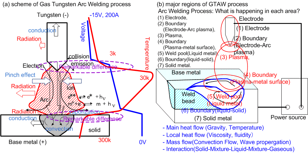
Here is the illustration from the author of the paper that Plasma56 referenced, and here's an High Frequency pilot arc plasma ignition on some possible pipe or round stock below, and 4 various shaped plasma streams based on time exposure in milliseconds...

Respectfully for the most part,
Henry
Parent - - By Plasma56 (**) Date 10-01-2014 00:28
Hi Henry.
I think "we" need to get out more my friend.

That high frequency current. Isn't that something freaky. First time I was shown that I knew I had to have one. Fact it came with a welding power source was a bonus. Big old boat anchor but it did a job or two. 30 years old and I'm on my third bottle of Argon. Would have been 2 bottles but I forgot to shut the bottle down one evening.

But I think we are getting somewhere talking GTAW.
Hey...raising eyebrows!

Not that I don't think we are to far off of the same page. I think we are on the same page.
The picture Lawrence presented I think we might both agree, that if a person visualized how the direction of the grooves rolling marbles changed, the path could be changed for the marbles to follow? Maybe, if the size of marble changed in relation to the groove length we could vary the flow of marbles?

While my pictures provided limited support, I implied the intensity of the high frequency arc reflected a greater focus to a perceived centering of a circumference with a more obtuse ground tungsten than the more acute angled tungsten profile.  I think if ones views our discussion with open eyes, reviews the information, they might suppose that the less resistant the path, the less the effort required? Maybe? More mush less slush?

But to clear up the "blunting" to the "sharpened tip" regardless of degree of taper, I offer in agreement the purpose is primarily arc stabilization, focus. I'm in no argument with that statement. I might also mention, regardless of taper, the diameter of the tip end removed will then effect this focus. The physics are playing havic. And like milking a cow, some kind of squeeze is taking place.

Your a welder. I'm a welder. Some where between solid and liquid is mush. That mush or degree of fluidity, viscosety in the weld pool is what I was taught to be construed as the noticeable "voltage factor" in the process. This is where I think we fell apart. But we are on the same page.

Most of us when learning to weld, learn to manage what we are shown. Eventually we understand the variables presented, manipulate them a bit and weld with them. We might do it a little faster, and more consistant over time, but rarely do we change what we were shown.

You didn't mention my two angle grind and a blunt. lol.

All good.

Oh yea...I cleaned my key board but the keys are still sticky. Not that it would improve my spelling, but I take ownership of that fault for not spell checking. I'm just saying...
But if it's going to add a greater degree of credibility remember I am a product of public education and lazy to a fault.

No hard feelings.
Parent - By ssbn727 (*****) Date 10-02-2014 00:52 Edited 10-02-2014 06:33
None taken Plasma56... actually I wasn't really focusing on your grammar or spelling at all... I was merely disappointed that the publisher of that paper didn't proof read it better if at all then again because of the author's origin, more than likely it was a language issue -that's all...  heck, even I make spelling mistakes on occasion as well as grammatical errors from time to time so I'm the last one being overly critical regarding another persons spelling and use of grammar unless that is, when the individual is a chronic repeat offender and only with the intent of educating and/or enlightening the individual...

Overall, yes I do agree that basically speaking we are on the same page... I believe the issue is the method of delivery as well as describing - elaborating of various points involved is where we are different to say the least yet, it's for the most part refreshing to witness the proofs of individuality in action if you will - in this here forum... So yes indeed no hard feelings at all...

And while we're still thinking about GTAW, here is some interesting information in the form of articles, and manual(s) from Miller Electric covering the fundamentals of GTAW...

This .pdf describes GTAW and offer guidelines to weld with an inverter type power source... A large portion cover AC welding of Aluminum yet, there's also coverage of DC current, differences in polarity, tungsten prep, HF basics with respect to various arc starting methods used also... A nice pamphlet to have when welding with an inverter type power source.

http://www.greatnorthernprepper.com/wp-content/uploads/2013/01/Guidelines-for-Gas-Tungsten-Arc-Welding-2008.pdf

Here's a version of the Miller Guidelines booklet that was a German manual translated to English? At least that's how the booklet is described.:surprised::lol:

http://www.germanmanuals.com/images/TIGBook.pdf

Here's another guide that is informative as well:

http://www.techtrain123.com/publicdownloadsallfiles/GAS%20TUNGSTEN%20ARC%20WELDING.pdf

With regards to Base Metal Temperature in Gas Tungsten Arc Welding, here's an interesting article: Elimination of interfering radiation from the arc and tungsten electrode
are found to be required for accurate infrared temperature measurements of base metal temperature:

http://www.aws.org/wj/supplement/Farson/farson.html 

"To strike the welding arc, a high frequency generator (similar to a Tesla coil) provides an electric spark; this spark is a conductive path for the welding current through the shielding gas and allows the arc to be initiated while the electrode and the workpiece are separated, typically about 1.5–3 mm (0.06–0.12 in) apart. The electric arc produced can reach temperatures of at least 5000° C. This high voltage, high frequency burst can be damaging to some vehicle electrical systems and electronics, because induced voltages on vehicle wiring can also cause small conductive sparks in the vehicle wiring or within semiconductor packaging. Vehicle 12V power may conduct across these ionized paths, driven by the high-current 12V vehicle battery. These currents can be sufficiently destructive as to disable the vehicle; thus the warning to disconnect the vehicle battery power from both +12 and ground before using welding equipment on vehicles." Jeffus 2002, p. 378 & Lincoln Electric 1994, p. 9.4–7.

A patent on a new type of HF assisted arc initiation.. "Arc welding with synchronized high frequency assist arc initiation." :

http://www.google.com/patents/WO2014135964A2?cl=en

Well, Toey did ask me and probably other folks in here as well to mentor him regarding the wide range of topics that make up various factors and aspects regarding GTAW...
So in this regard, I aim to please!:eek::surprised::smile::grin::lol::twisted::yell::lol::roll::wink::cool:

Modelling of fundamental Phenomena in Welds.:

http://www.osti.gov/scitech/servlets/purl/10178263

Exploring Infrared Sensoring for Real Time Welding Defects Monitoring in GTAW.:

http://www.ncbi.nlm.nih.gov/pmc/articles/PMC3247742/

A Weld Defects Detection System Based on a Spectrometer.:

http://www.ncbi.nlm.nih.gov/pmc/articles/PMC3348795/

Defect Detection in Arc-Welding Processes by Means of the Line-to-Continuum Method and Feature Selection.:

http://www.ncbi.nlm.nih.gov/pmc/articles/PMC3292081/

Review of Arc Efficiency Values for Gas Tungsten Arc Welding.:

http://hv.diva-portal.org/smash/get/diva2:523654/FULLTEXT01.pdf

Optimization and Non-destructive Test Analysis of SS316L Weldments Using GTAW.:

http://www.scielo.br/pdf/mr/v17n1/aop_191413.pdf

Progress Report on a Fully Automatic Gas Tungsten Arc Welding (GTAW) System Development.:

http://www.osti.gov/scitech/servlets/purl/10106005

A comparison of the physics of Gas Tungsten Arc Welding (GTAW), Electron Beam Welding (EBW), and Laser Beam Welding (LBW).:

http://ntrs.nasa.gov/archive/nasa/casi.ntrs.nasa.gov/19860002006.pdf

http://ntrs.nasa.gov/search.jsp?R=19860002006

Gas tungsten arc welding in a microgravity environment: Work done on GAS payload G-169.:

http://ntrs.nasa.gov/archive/nasa/casi.ntrs.nasa.gov/19870010873.pdf

Electrode carrying wire for GTAW welding,:

http://ntrs.nasa.gov/archive/nasa/casi.ntrs.nasa.gov/19900016852.pdf

Patent for a GTAW Torch with a coaxial vision camera within the torch.:

http://ntrs.nasa.gov/archive/nasa/casi.ntrs.nasa.gov/20080008217.pdf

Grain refinement control in TIG arc welding.:

http://ntrs.nasa.gov/archive/nasa/casi.ntrs.nasa.gov/19750011611.pdf

Study of Radiographic Linear Indications and Subsequent Microstructural Features in Gas Tungsten Arc Welds of Inconel 718.:

http://ntrs.nasa.gov/archive/nasa/casi.ntrs.nasa.gov/20080002286.pdf

Surface Temperature Distribution of GTA Weld Pools on Thin-Plate 304 Stainless Steel.:

http://aws.perusion.com/wj/supplement/WJ_1995_11_s353.pdf

Humping formation in high current GTA welding.:

https://www.ualberta.ca/~ccwj/publications/Papers/Conference/Humping/Mendez%20-%20Humping%20Formation%20in%20High%20Current%20GTA%20Welding.pdf

INVESTIGATION OF FLOW DYNAMICS AND PLASTIC DEFORMATION IN ARC WELDING USING SPH.:

http://www.cfd.com.au/cfd_conf09/PDFs/124DAS.pdf

Double Stage Plasma Arc Pipe Welding Process.:

http://www.aws.org/wj/supplement/WJ_2012_12_s346.pdf

Welding Science: A New Look at a Fundamental Technology.:

https://str.llnl.gov/str/November01/Elmer.html

Visiting professor welds new partnerships.:

https://www.llnl.gov/news/aroundthelab/2014/Aug/ATL_0080814_baker.html 

Direct Observations of Austenite, Bainite and Martensite Formation During Arc Welding of 1045 Steel using Time Resolved X-Ray Diffraction.:

https://e-reports-ext.llnl.gov/pdf/305013.pdf

Numerical Modeling of Enhanced Nitrogen Dissolution During Gas Tungsten Welding.:

https://e-reports-ext.llnl.gov/pdf/243973.pdf

Comparison Between Keyhole Weld Model and Laser Welding Experiments.:

https://e-reports-ext.llnl.gov/pdf/245608.pdf

Synchrotron-Based Experimental Investigations and Numerical Modeling of the Kinetics of Phase Transformations in the Heat Affected Zone of Welds.:

https://e-reports-ext.llnl.gov/pdf/238810.pdf

Influence of Thermal Aging on the Mechanical and Corrosion Properties of C-22 Alloy Welds.:

https://e-reports-ext.llnl.gov/pdf/238610.pdf

Keyhole TIG Welding Process.:

http://www.msm.cam.ac.uk/phase-trans/2004/CSIRO2/keyhole.html

http://www.k-tig.com/how-it-works/

http://www.k-tig.com/brochure/  

There's more but, I have to fix a billing question for my cable TV service so I'll end it here.

Respectfully,
Henry
Up Topic Welding Industry / Technical Discussions / Vertex angel (GTAW) less or more give good penetration
1 2 Previous Next  

Powered by mwForum 2.29.2 © 1999-2013 Markus Wichitill