Not logged inAmerican Welding Society Forum
Forum AWS Website Help Search Login
Up Topic Welding Industry / Inspection & Qualification / UT inspection question
- - By Bill M (***) Date 02-06-2007 13:40
AWS D1.1
Inspecting an unground plate butt joint with w.t. of 3-1/2".  The inspector is required to use procedure #5.   Table 6.7 specifies #5 as 45 deg. top quarter, 70 deg middle half, 70 deg bottom quarter.

Scanning with the 45deg. transducer to inspect the top quarter is made in leg 2.  The scanning area is marked on the plate to assist the inspector in keeping the transducer the correct distance from the weld to keep the sound in the top quarter, (leg 2).

So the inspector is concentrating on the top quarter weld volume, but as happens, slides the transducer forward ocasionally.  Suddenly, the inspector gets an indication in the bottom quarter of the weld with the 45 deg.  The indication is of short length, yet considered rejectable due to defect rating.  The indication is detectable with the 70 deg. transducer in the same location, but not of rejectable amplitude.  The indication is detectable from the opposite side of the weld as well with the 70 deg, but also not of rejectable amplitude.

Is it rejectable?  Is it rejectable if it is in the root?
Parent - - By thirdeye (***) Date 02-06-2007 14:24 Edited 02-06-2007 14:34
Knowing that some indications sometimes will be oriented in such a way they might not give the best reflection when following a specific scanning procedure, you pose a very valid question.  On top of that, considering that the root area is an area where indications are likely to occur, and that their presence could be the most detrimental are some things to consider.  Another thing to consider is the fact that an unground weld can produce some expected echo's, but it sounds like in this case it has been confirmed from face B and plotted out...

That being said, AWS does allow variations in procedure, equipment and acceptance standards upon agreement with the Engineer.  Since this sounds like a straight forward kind of joint configuration I'm not suggesting that an inspector should routinely "dig for potatoes" by using different procedures or testing angles until something is found, but in your case something was located during the normal performance of an examination.  I have seen plenty of inspectors in this situation simply tickle the indication rating forcing the repair, but of course, that is not ethical.

I would plot it, document it on paper and send it up the ladder for disposition.  Let us know how this works out.

~thirdeye~
Parent - - By Bill M (***) Date 02-06-2007 14:50
Thanks for the advice Thirdeye-

I discussed it with other techs I know...they said that if it is not in the required scanning volume for that particular angle, they typically would ignore it.

It was just a unintentional scanning movement that caught this particular indication.  If it is rejectable, should he go back and scan the balance of the weld with a 45 deg for the middle and bottom?

I have read D1.1 "6.27.6".  So if an inspector is scanning away and find an indication that is say, a +12(when +3 is acceptable regardless of length) in the fusion face, does that mean for ANY such indication that might be interpreted to be a fusion indication or in the root volume, the inspector has to stop, and look at it with a 70, 60, & 45 deg? 
Parent - - By hogan (****) Date 02-06-2007 15:23
aws doese not require the ut tech to name an indication. even if it did, i would guess that the average aws ut tech would only be correct at best 50% of the time. some indications have certain charistics, and knowing the joint configeration and welding process will help in narrowing down what it could be, but there is no reliable method for naming indications found with shearwave inspection.
Parent - By thirdeye (***) Date 02-06-2007 18:51 Edited 02-06-2007 18:56
hogan,

You are correct, but in this case the Code refers to "indications in the root areas of groove welds in butt joints and along the fusion face of all welds".  No identification of indications by the technician is called for.

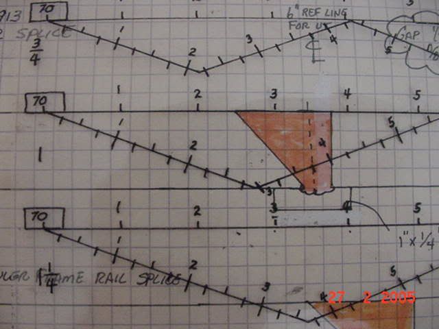
Like you said, a joint plot is mandatory so you know exactly where the indication is located to know if  further evaluation is required.  The guys I work with make a plot of all UT joints and we use clear overlays for sound path.  Here is an example of an overlay on a 1" thick joint sketch with a backing bar.


~thirdeye~
Parent - - By thirdeye (***) Date 02-06-2007 15:41
Technically the other tech's have a valid point, but as I pointed out...this indication may be non-typical and since you found it, explore it so a basis for acceptance or rejection can be discussed.

Your second question falls under my term "digging for potatoes". So unless instructed to do additional scanning by the Engineer after he reviewed you previous finding, I would not.  FYI, Often times when UTing inservice repairs on equipment, cracking in the root area of certain joints is a problem.  In this case some of my customers have a mandatory shop practice to perform additional scanning. Indication rating is usually not considered if a reflector appears in a zone that has proven to be a problem.

Third question...T,Y and K connections are especially tricky and that requirement is to protect you and the client that the acceptance or rejection has been confirmed with every possible angle.  My experience with those joints is limited.. I would expect that you would be hard pressed to find that a +12  could turn into a rejectable when a +3 is acceptable, but the answer is yes.  Follow the procedure.  This question has Kip Mankenberg written all over it....maybe he will jump in.

~thirdeye~
Parent - - By hogan (****) Date 02-06-2007 19:14
instead of using procedure 5 could you use 1G?
Parent - By thirdeye (***) Date 02-06-2007 19:26
Hogan,

Bill mentioned that the plate was unground, I took that to mean the weld was not ground. Are you thinking grinding the entire joint and forget the 45° all together? Or grinding the area around the indication and seeing what effect that has?  I know a little surface finessing has saved me many times. LOL

~thirdeye~
Parent - - By Bill M (***) Date 02-06-2007 19:28
Yes, I guess I could.

The joint is about 3-1/2" wide... a nominal 3/32" tall reinforcement, and 48 inches long.   (since I have 4 to do) Thats about 18 pounds of steel to turn to grinding dust.  I will pack a lunch and start grinding!!

On second thought...If I picked up a grinder and even pointed it at those pretty sub arc cover passes, I tell ya...those welders would have no sence of humor what so ever!
Parent - - By Bill M (***) Date 02-06-2007 19:34
An RT crew is coming in for some other work anyway so..I am going to take a spot RT shot there.
Parent - - By thirdeye (***) Date 02-06-2007 19:40
Bill,

Good luck with the definition of a radiogrqph through 3-1/2" of steel.  Is the access to the joint good enough to place the film on the side of the joint closest to the indication?  Can they get some decent source to film distance?

~thirdeye~
Parent - - By Bill M (***) Date 02-06-2007 19:45
Fortunately yes, It is wide open on each end so far, and the film will be closer to the indication.
Like you are suggesting, it will be a somewhat long exposure and i am sure a grainy view.  I am just curious now.
Parent - - By hogan (****) Date 02-06-2007 19:50
i believe that aws requires the use of cobalt for thickness over 2 1/2", might want to verify the rt crew knows it will be done with cobalt.
Parent - By Bill M (***) Date 02-06-2007 19:54
thanks
Parent - - By thirdeye (***) Date 02-06-2007 20:06
hogan,

I believe that AWS prohibits the use of Cobalt when the material thickness is less than 2-1/2".  If you have the time, Iridium can still be used for any thickness.  Of course, at some time the usefulness of Iridium takes a nose dive as thickness increases. For confirming something like this indication, I'll bet a 15" SFD would work and if the Iridium source is hot enough, will make a much better picture.

I don't have the Code in front of me, but is composite viewing allowed by AWS?

~thirdeye~
Parent - - By CWI555 (*****) Date 02-07-2007 21:57
If I recollect properly, 3.5" is to much for Iridium to get any valid image on. Internal scatter and attenuation at that thickness will likely destroy the image outright, assuming you got an image. A 100 CI source would be attenuated to .781 ci roughly calculated on half value layers without consideration of internal scatter increasing the attenuation factor as it goes into the last inch. Assuming a class II film at 3.5R exposure facture and 24" SFD your looking at in excess of a 3 hour shot. I've shot a lot of x ray, and have never been able to an image with any measurable sensitivity beyond 3.25" of steel with Iridium and then it was very fuzzy. Maybe I've been to long away from performing radiography, so if you think my numbers are incorrect please feel free to post a correction.
Parent - - By thirdeye (***) Date 02-07-2007 23:11 Edited 02-08-2007 00:56
CWI555,

Using your parameters, and a 100ci Iridium source, you are right on with your exposure calculations, give or take 10 minutes.  But in this case 24" SFD most likely would not be necessary to prove the existence of the indication.  On 3" to 3-1/2" material thickness, we have the best luck using a film like Agfa D4 with a film factor of 2.5.   At 15" SFD that would give you an exposure time of 50 minutes, and at 20" SFD the exposure time would only be 90 minutes.

If you opted to go with composite viewing using D4, those times would roughly be cut in half. I actually prefer this technique on something like this due to the slight adjustments you can make when reviewing the films.

~thirdeye~
Parent - - By CWI555 (*****) Date 02-08-2007 05:16 Edited 02-08-2007 05:20
You can do anything when it comes to informational shots. I'm still a bit dubious as to being able to get a valid image at 3.5" of steel. The UG (assuming a .168 source cross section) at 24" would be .028, 20" would be .037, and at 15" would be .05. Only the 20" and 24" shot would be code withstanding concerns in regards to originating source.  There may be some codes that allow iridium at this thickness but if there is I am unaware of it.
My comments were in regards to a code shot. Now if you want to shoot something just to get an idea whats in it without concern of code, 15" might work with a class 1 film as you've mentioned, but the image will still be on the fuzzy side. As for composite viewing, I don't have the code in front of me either, but I seem to recall AWS refering to Section V, if that is correct then composite viewing is allowed.

Parent - - By thirdeye (***) Date 02-08-2007 14:29
Good morning CWI555,

Once again, your calculations are dead on.  Increasing the SFD to 18" will put you at .040 Ug, and would increase exposure times to either 1:10 or about 40 minutes depending on technique. 

But remember Bill had located the indication in the root of the joint during the UT scan?  And he also confirmed that the film could be placed on that face of the joint?  Now the indication would (conservatively) be within 1" of the film and maybe closer.  The enlargement or distortion (Ug) of the suspect indication would be much less than if the indication was located in the upper 1" of the joint. I'm sure you see where I'm headed with this ... using a 15" SFD would actually give you 14+" source-to-indication distance (instead of the general 11.5" STO distance),  thus reducing the Ug of that zone of the joint to just over .01.  Of course using both a  source side and film side penetrameter is recommended.

I don't think there was ever any doubt about the graininess of films through that thickness of material, that is why I wished Bill "good luck" when referring to definition on the film.  I'll look through some client archives and if I can locate some radiographs with Iridium through similar material thickness, I'll post one.

~thirdeye~
Parent - - By CWI555 (*****) Date 02-09-2007 02:52 Edited 02-09-2007 08:15
Good evening thirdeye,

First I need to clarify; I am not arguing in a negative sense, its as much refreshing my memory on theory I haven't run through my head in a few years so please indulge me for the moment. It's not meant in a negative light.

From strictly a ug stand point, you are spot on in regards to indication ug. However, the ug calculation doesn't take into account the amount of internal x,y,z scatter. while it may be on the back side of the shot, at that thickness, it will be coming from all directions. This is inherent due to
the energy variations in IR192. 206-612 kVp according to ISO 5579. That translates to multiple wavelengths, and different attenuation rates
for the same reason. (which vary depending on what side of the fence you land on in respect to Planck or Maxwell ) Compton scattering will produce 58 degrees theta, and -38 phi on the upper end and on the lower end the same theta, but a -52 phi. The higher energy 612 will be the shorter wavelength/more energetic photon and penetrate further before scattering inversely so with the longer wavelength. (stretching out one to many dusty braincells on this one) This if I recollect will lead to photoelectric effect and incoherent/coherent attenuation (the math of which escapes me at the moment) The end result is only the higher energy photons will make it to the back side of the weld in question. Their impingement angle will be affected by Compton scattering at the angles listed above without respect to the flaw in question except in the lessening of material inherent in the flaw. Those impingement angles due to the Compton scattering will play havoc with the resulting image as those angles are further bent until the photoelectric kicks in and in effect giving you nearly all axis scatter. It's those effects that are not accounted for by standard ug calcs and why the specific material and steel minimum and maximum recommendations/requirements are made in various codes. You can calculate the flaw ug but at this thickness, that's the least of the worries with Ir192.

Therein is the limit of my understanding on the matter, if someone else has further information I missed please feel free to post.

That information for whatever it's worth.
Parent - - By thirdeye (***) Date 02-09-2007 08:15
CWI555

Heck, I didn't get the impression we were having an argument either.  I'm really going to have to try and dig up some client radiographs of thick material using Iridium and get a digital photograph of them to post.

~thirdeye~
Parent - - By CWI555 (*****) Date 02-09-2007 08:26
Glad you took it the right way, some have gotten an attitude when I try to go into detail.
Parent - - By thirdeye (***) Date 02-09-2007 16:16
CWI555

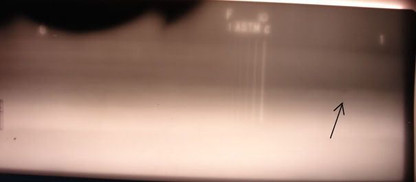
Here is the closest thing I can come up with .... actually, the exposure parameters here are way less than ideal, so maybe it is a good example.  This is a technique film of a head to 20" od X 3" shell on a high pressure well-head pressure vessel.  Due to forming of the bullet type of heads, additional sub-arc passes were added to the head side of the joint to achieve the correct taper.  That combined with lack of contact between the cassette and that portion of the head is why the density lightens up south of the pene.  An Iridium source was used with a panoramic exposure technique. The STO is 7", putting the Ug numbers off scale. This film is Agfa D5, which is a tick faster that the D4 we had discussed earlier.  The pene is film side on the production joints since there is limited access to the inside of the vessel.  At the arrow you can see some incomplete penetration at the root.  The dark area to the left of the pene is a partial hole for a 3" nozzle.  Following RT the remainder of the hole is cut away, taking some of the weld seam with it.


Just some background .... the technique was accepted by the AI and customer based on the ability to see the penetrameter image.  (The other choice would have been a DWE through a 6" thickness using Cobalt). As I recall, a mock-up exposure on the end of a joint of pipe or on the procedure coupon using both a source side and film side pene was taken and submitted with the technique sheet.  The film selection was upgraded to Agfa D4 for production rediography.

~thirdeye~
Parent - - By hogan (****) Date 02-09-2007 16:34
when can't you see a film side wire pen
Parent - - By thirdeye (***) Date 02-09-2007 17:01
hogan,

The purpose of the technique film from the weld procedure I mentioned was to prove sensitivity of both pene's and show comparison between the two.  But since the source side one could not be used during production radiography, there was no choice but to accept the use of the film side one.  By the way on this film (D5) it does show one wire smaller than required.  I believe that the D4 film I mentioned may have been selected in order to show the required wire from the source side pene.

~thirdeye~
Parent - By hogan (****) Date 02-09-2007 17:16
what i was getting at is that the wires are much easyer to see.
Parent - By CWI555 (*****) Date 02-09-2007 23:56 Edited 02-10-2007 04:09
An earlier quote from myself "I've shot a lot of x ray, and have never been able to an image with any measurable sensitivity beyond 3.25" of steel with Iridium" The set C ranges from .032" to .100" on the wires. What I notice about the photograph is that all the visible wires are fuzzy on 1/4" less material than I quoted you as critical. In the thickness range of that radiograph, I am willing to bet breakfast that the lead leaders depicted there are haloed from the odd angle scatter even at 3". I would further assert that if that had been shot source side, it would be iffy seeing the .100 wire, much less any of the rest of them. If the AI bought it off and your customer is happy, I don't think you have any problems, but I wouldn't have any warm fuzzy that I found everything that could be found with normal radiographic techniques.

Bottom line to me personally is, I'll stay away from this if at all possible. Another reason I hung up the dosimeters and techops. I am getting to old and fat to be chasin rays these days. With the proper calibration and reference blocks I would have a warm fuzzy in regards to performing an exam like that with UT. Without the concern of the cobalt energy levels and inherent problems of it. Just my humble opinion.
Parent - - By thirdeye (***) Date 02-06-2007 19:55
That will help ..... In a case like this I like to use film side location markers, it will be easier to pin-point your area of interest without having to worry about the enlargement factor associated with source side markers.

Let us know how this turns out.  It seems I always learn something when using RT back up following UT.

~thirdeye~
Parent - - By hogan (****) Date 02-06-2007 21:33
thirdeye,
you are correct on the cobalt use, i went off of memory (can get me in trouble).
Parent - - By kipman (***) Date 02-09-2007 06:28
Gentlemen,
With all due respect, I believe RT would be useless in this case.  As stated in the initial post, the reflector is better seen with a 45 than with a 70.  This indicates that the orientation of the reflector is such that it might not be seen with RT.  Were the opposite true (i.e. seen better with a 70 than with a 45) it would be more likely that RT would see the discontinuity.
Mankenberg
Parent - - By thirdeye (***) Date 02-09-2007 08:02
Kip,

I think we are all in agreement that overall radiographic quality will suffer because of definition, sensitivity and graininess.  Nonetheless, since Bill had an x-ray crew available it was certainly worth a shot or two because the final disposition of the indication(s) in question looks like it may come from Engineering. The more information available to them the better.  I would think that an exploratory dig would would have been an option as well.....

CWI555 and I have taken this thread slightly off track in our discussions of the efficiency of Iridium verses Cobalt but honestly, this type of exchange of ideas  is one of the things I enjoy about online forms.

I hope that Bill posts a follow-up and let's us know how things turned out.

~thirdeye~
Parent - - By Bill M (***) Date 02-19-2007 16:50
The RT shot was not conclusive by any means...but did show some really small, fuzzy, less dense indications in the UT indication area, none really linear, or of significant length.  We elected to remove it from the inside, and the follow-up UT was clean.  Since confession is good for the soul...I later learned that there was some problems with the flame cut equipment during the weld prep cutting, and this particular torch cut weld prep was not ground as well as it should have been, and possible cutting indention / dross contamination is also suspect.
All's well that ends well...and the flogging will continue here until moral improves!!
Parent - By CWI555 (*****) Date 02-20-2007 02:05
The flogging? LOL
Up Topic Welding Industry / Inspection & Qualification / UT inspection question

Powered by mwForum 2.29.2 © 1999-2013 Markus Wichitill