Not logged inAmerican Welding Society Forum
Forum AWS Website Help Search Login
Up Topic Welding Industry / Inspection & Qualification / Mag partical testing over paint
1 2 Previous Next  
- - By MDG Custom Weld (***) Date 02-23-2007 19:02
I just got a call from a customer that fabricated some pallet transfer stations for an automotive plant.  A few of the welds failed in the field, and the auto plant brought in a third party to mag partical test the rest of the transfer stations.  They sent me some pics of the parts they tested that were labled as "suspect" for lack of fusion.  All of these parts are painted with a thick industrial enamal paint.  None of the parts they labled as suspect showed signs of the paint being removed at the weld, or where the prods or horn were attached.  Is it standard to get good results from mag partical testing througt paint?  I first questioned the test report because it has no company contact information for the testing company, and only list the Techincians name and the Level II status.  It has not certification numbers of the Technician, or what the Level II is for.  Should I question the report?
Thanks,
Mark
Parent - - By hogan (****) Date 02-23-2007 19:11
does it state what code the inspection was performed to, and evaluated to?
Parent - - By MDG Custom Weld (***) Date 02-23-2007 19:39
Well, in short yes.  The report states "MT.AWS1.Rev.1" as the procedure and the code "AWS D1.1-2006".  However, the job was not built to any required code.  This inspection was only done because we have had 3 other component failures on these same parts, but all have been linked to design flaws.  I was brought in only after the first 3 failures occurred, so hind site for my customer is now 20/20.  Anyway, my customer build these to print, and is reluctant accept responsibility for the design related fatigue failures, however the auto plant (who designed these) is reluctant to accept any blame either.  So here I am, in the middle trying to protect my customer while maintaining my integrity.  Now that we showed the mechanical failures to date were design related, and not a welding failure, the auto plant is grasping anything they can to pin the blame elsewhere.
Parent - - By hogan (****) Date 02-23-2007 21:02
i do not believe that mt can be performed through a coating as thick as you describe in accordance with aws d1.1 (astm e709). there is a good chance that defects likely to be in the parts would be masked by the coating.
Parent - - By MDG Custom Weld (***) Date 02-23-2007 21:26
Thanks Hogan, that's what I thought too but not being the Level I mag expert, I wanted to make sure.
Parent - - By NDTIII (***) Date 02-24-2007 04:41
Hogan is correct. You cannot perform MT through thick paint. Whether the code permits it or not. It does not work.
The technicians should be certified to ASNT Recommended Practice SNT-TC-1A.
Yes I would definitely question those reports.
Parent - By MDG Custom Weld (***) Date 02-24-2007 11:42
Thanks guys, now I know I am on the right track!
Parent - - By 803056 (*****) Date 02-25-2007 21:56
Should you question the report? On what grounds? Were there photographs of the magnetic particle indications? Are you qualified to perform the NDT or comment on the procedure used? Have you looked at the welds that were questioned? Look at the welds before you make any comments about the weldments or the inspection reports. You never know, the report may be correct.

I would expect that the NDT technician used an AC yoke or perhaps an AC/DC yoke if the magnetic particle test was performed in the field without removing the paint (paint would have to be removed to provide electrical contact if prods were used for the testing).

The magnetic particle test (or other NDT method) is often applied as a means of gathering information. The technician should make reference to any NDT procedures used or perhaps a reference to a code for comparison purposes (not necessarily as a basis or acceptance or rejection if the part was not fabricated to a code or standard).

The "sensitivity" of the magnetic particle test is diminished as the thickness of the paint increases. That being the case, the formation of a magnetic particle indication is less pronounced as the paint thickness increases. Any magnetic particle indication formed would be more distinct if the weld was free of paint, but the fact that a MT indication formed is a good clue that a discontinuity was present. Based on the indication that was observed, the technician or client can make a decision on what steps to take, i.e., stripping the paint for more complete testing, selecting a different NDT technique, etc. The bottom line is that the magnetic particle test results may be adversely affected by paint thickness, but the test is still worthwhile as a screening technique and a factor in the decision making process.

I often use MT with an AC yoke in the field as a means of confirming overlap conditions and other deleterious conditions in steel materials that can be concealed by paint. My report includes a statement that the steel was in the painted condition. MT through the paint is a good alternative to telling the owner and contractor that the welds can't be inspected because the welds have to be in the as-welded condition to perform the inspection (not always true). You can bet your last dollar that if I detect a discontinuity through the paint, it will not disappear once the paint is removed. That may be the course of action, i.e., removing all the paint, but it is easier to justify once MT has identified an unacceptable condition.

Why wasn't the material inspected at the fabricator's facility? Third party inspection by the owner is not always required if it wasn't included in the original contract or if the part or assembly is a manufactured product that isn't addressed by a code. The owner may decide to perform some type of NDT if the manufactured material is not performing as expected and there is a need to determine the cause of a failure. As in this case, was the failure due to weld quality related issues or design issues?

Good luck with your repairs.

Best regards - Al
Parent - - By MDG Custom Weld (***) Date 02-26-2007 14:49
Al, Thanks for the insight.
To answer your questions.  I questioned it because it has photos of one piece that was tested, however the pic was NOT of the actual test being performed.  The report does NOT list any contact information for the testing company, it just list their name, the actual person's cert number, no phone, address, city, ect.  I do NOT have any NDT certs, so I claim no expertise on the results.  I DO have CWI/CWE certs, and did see the welds (only from pics) before I made comment.  The report does list as A/C Yoke Wet as the testing method.  The report may have good results, I just question the validity of the report based on what I feel is a lack of proper documentation. 

Also, the report had a disclaimer that stated..and I quote.."THIS REPORT IS EXPRESSLY LIMITED TO 'testing company name removed' INTERPRETATION OF THE RESULTS OBTAINED FROM THE TEST SPECIFIED AND DOES NOT CONSTITUTE A RESPRESENTATION WARRANTY OR GUARANTY OF THE ACTUAL CONDITION OF THE MATERIALS TESTED. 'testing company name removed' expressly disclaims any responsibility for any loss cost damage or expense including personal injury or death caused by or attributed to 'testing company name removed' misinterpretation of conditions or the performance of any test."

Is this standard?  When we provide inspection reports, we stand behind our results and our ability to properly inspect as we are certified to.  We are not allowed to "misinterpret" our inspection methods or results, that's why we are certified.  We are required to list our inspector's cert numbers, contact information, and company contacts.  These guys are supposed to be the "experts", why would they need such a disclaimer?

And lastly, the weld itself was PJP tube to plate with the radius of the tube making a single flare bevel, only down one side of the tube.  The part was then loaded with the root in tension, ultimately causing a fatigue failure from the root out.  A simple design review early on identified this as a problem, but the end user stood behind their design, so fabrication continued.  Now that the joint in question failed (as suspected), they are claiming the weld failed because of lack of fusion at the weld toes, however the pics I have seen so far show a root failure because of improper design and loading.  I am expecting to see the actual parts this week sometime.  Maybe they will tell the story with no question.
Thanks to all of you for your NDT wisdom in mag particle.
Mark
Parent - By hogan (****) Date 02-26-2007 15:14
that is a commen statement on a report from a testing lsb.
Parent - - By thirdeye (***) Date 02-26-2007 15:35
Of course, the preferred surface would be as welded and clean of any foreign material.  It is however possible to pull some indications through paint, I did some MT through paint just last week on joints that have had a history of poor fusion where run-off tabs are removed. 4 out of 10 joints showed indications. This is not standard procedure but production got ahead of inspection and then did not want to remove the paint.  After the test through paint, all of the joints were cleaned and one additional joint disclosed a lack of fusion line.

I'm not sure if I go along with the selection of AC and Wet MT for this situation.

That disclaimer is for the most part industry standard.  Some go even further specifically mentioning "not responsible for errors and omissions" and mention phrases like "at time of inspection".

~thirdeye~
Parent - - By MDG Custom Weld (***) Date 02-26-2007 15:43
I'm suprised that someone would agree with such a disclaimer.  I do totally understand in our "pass the buck" sue happy society though.  I am waiting to see the parts in question this week, that should really show the failure mode.
Parent - - By js55 (*****) Date 02-26-2007 16:13
Somebody help me out here. "Lack of fusion" through paint with MT?
Parent - By thirdeye (***) Date 02-26-2007 19:15
js55

Yes.  I think for the most part we are in agreement that it is possible for indications to be shown through paint.

~thirdeye~
Parent - - By thirdeye (***) Date 02-26-2007 19:08
Well, I guess the lawyers agree.  LOL    Here is the disclaimer we use.  Over time it has grown slightly and the wording has changed, but in 30 years, I don't recall anyone objecting to it.   I can't say how it would fare in a court of law as that is one thing we have never tested.

~thirdeye~

The information reported appears to be a reasonable sample of the condition of this item, but is not judged to represent the condition of this item with absolute certainty.  Accordingly, XYZ Corporation  has applied ordinary skill in making the inspections and shall not be held liable for errors or omissions of any kind.  The manufacturer / owner must satisfy itself as to the adequacy and accuracy of the evaluation.  The results reported represent opinions only and are not to be considered as warranties or guaranties of quality.  Nothing herein shall be construed to be a guaranty against loss occasioned by failure of the structure upon which the examination is made.  XYZ Corporation assumes no responsibility for misinterpretation of indications.
Parent - - By dmilesdot (**) Date 02-26-2007 19:46
Even if the mag. particle was done for information only, I would question several things on this particular exam.  How thick is the paint? AC wet on a painted surface is highly questionable as to the sensitivity of the exam.  Also since it doesnt say if it was visable or flourescent, the color of the paint could also decrease sensitivity.  In my opinion the exam is worthless.
Parent - By thirdeye (***) Date 02-26-2007 19:59
Like I said earlier, I'm not sure I agree the AC wet selection either.  For some input on coating thickness, here is an ASNT article discussing MT & eddy current examinations where coatings are involved.

http://www.asnt.org/publications/materialseval/solution/feb98solution/feb98sol.htm

Mark, I hope you follow up after you get a look at the parts.

~thirdeye~
Parent - - By jwright650 (*****) Date 02-26-2007 20:28
I didn't read the entire thread so forgive me if this has been covered already.
Are you sure that the MT was done after painting? I guess you could use a DFT gage to determine the coating thickness and go from there.

I have done a little checking with A/C dry powder when paint was already applied, but it was more that I suspected something and that the MT confirmed my suspicion. 
Parent - - By MDG Custom Weld (***) Date 02-26-2007 21:38
Dmilesdot:  I did not mention this before, but the particle is 14AM with a Magnaflux black light with no intensitity measurments.
Does this too add to the question of the report being suspect?

Again thanks to all of you.
I'll keep you informed once I see the parts.
Mark
Parent - - By jfwi (*) Date 02-26-2007 23:20 Edited 02-26-2007 23:22
FYI - Our written procedure requires that "it be demonstrated that indications can be detected through the maximum coating thickness applied." before actual testing.

Jerry
Parent - By NDTIII (***) Date 02-27-2007 04:54
Thank you Jerry. That would be the only way I would accept a MT exam through paint, and I emphasize "Only Way!!"
Parent - By CWI555 (*****) Date 03-04-2007 16:50
I would be surprised if you found any NDE company that didn't have such a disclaimer.
Parent - - By 803056 (*****) Date 02-27-2007 05:41
As Paul Harvey says, "and now the rest of the story."

Don't get me wrong. I'm not condoning poorly written reports, poor inspection techniques, etc. I just don't like to assume the "other person" is of dubious character because of a poorly written report. Also consider that the report provided by the client may not be the complete inspection report, it may consist of only those portions they consider to be relevant. Many reports list all the company information on the cover page and only the company logo on the pages that follow. 

Considering the conditions underwhich the MT was performed (less than ideal), I can see why the company providing the service would have the disclaimer. It's called "cover your butt when you know the testing conditions are not optimal and the test results can not be relied upon." The company performing the NDT may have requested the welded be stripped of all paint, but the owner may have refused to spend the money. We (that includes you) don't know all the facts. While wet fluorescent magnetic particle testing would not be my first choice, I might elect to use it if there was wet or oily residue present, assuming the paint did not "absorb" the wet magnetic particles. If wet fluorescent magnetic particles were used, it is understandable that no photographs of the magnetic particle indications were included in the report.

I still don't understand your concern that the tests performed are "questionable". Until you actually see the welds for yourself, you can only accept what is written at face value and accept the limitations of the information provided. You know that the MT was performed after some welds failed. You know that the MT was performed on painted parts that were in service for some period of time.

Like you, I am certified for the visual inspection of welds per QC1.  I would hate to recount some of the poorly written or documented "test reports" filed by some of our brethen. However, I usually accept the documents provided at face value, i.e., I assume the individual did the best he/she could operating under the conditions that existed at the time of the inspection. I may find out otherwise after I complete my examination, but I try to assume the individual doing the inspection or the test is not intentionally trying to mislead or provide false information to the client.

I'm sure you will have a better idea of the cause of the failures once you have the parts in-house and you can look them over. Would I suggest that you do or have additional testing performed. You bet I would, just like I would reinspect welds inspected by another CWI or I would repeat an ultrasonic test performed by another NDT technician.

I would be interested to know if GMAW short circuiting transfer was used by the original manufacturer (your client?). As CWIs, we all all too well aware of the fusion problems associated with GMAW-S. It sounds like an interesting problem and as is usually the case, there will not be many winners. Hopefully you will be the winner in this situation by fixing the problem welds and collecting a nice fee for your services.

The bottom line is that the tone of your inquiry made it sound like you were arming yourself to "attack" the integrity of the inspector, the report, and the company providing the service. My replies are intended to make you step back a little and consider the other side of the story. Don't shoot the messanger until you know the information provided is false.

Best regards - Al
Parent - - By MDG Custom Weld (***) Date 02-27-2007 11:58 Edited 02-27-2007 12:31
Again thanks Al.
I did not mean to attack the report given to me, I have in fact not even shared any of my (or anybody here) comments to my customer or the end user.  I was simply stating my concerns and "questions" of the report here as a means to gather further informaiton on the subject of which I am NOT an expert.  Using some of the opinions expressed here, I'm more confident than ever that further examination is required once I have the parts in question.

Oh, yeah it was GMAW-S.....of course:)
Parent - - By 803056 (*****) Date 02-27-2007 17:32
Paint or no paint, I am willing to bet that dry particle MT will reveal some areas of incomplete fusion between the weld beads and base metal of the "MIG" welds, especially at the beginning of the weld beads. I wouldn't be surprised to see some crater cracks as well.

I love GMAW-S. It's a money maker for those of us that inspect welds for a living. I've had entire projects involving plate materials, between 1/4 inch and 3/4 inch, welded with GMAW-S, that had to be gouged and rewelded. One project that was originally quoted as a three day job (random spot checks) turned into an eight month project where no welding could be performed unless I was on the site. As an inspector, you just have to love GMAW-S. I have one starting in a week or so where the contractor wants to use it. I can't tell them not to use it, it's their choice.

"Hello, Honey, book another week of vacation in the Carribean for next winter!"

Best regards - Al
Parent - - By NDTIII (***) Date 02-28-2007 04:34
Not with an AC Yoke you won't. I'll take that bet. Just how much do you have to lose?

You still have to demonstrate it before you do the examination. You can't just perform it through paint.
Parent - - By 803056 (*****) Date 02-28-2007 15:18
I use the continuous current, dry particle technique with an AC yoke to check weldments that have shop coat paint on a regular basis. It isn't unusual to be contacted by an owner after the steel is delivered to the site or to inspect something that is in service. The owner is not going to remove the paint unless there is cause to do so. It is costly and time consuming. Any discontinuity detected with the AC or DC yoke is not going to disappear once the paint is removed. I have even used leaches on one occasion where the contractor shut off the electricity because my findings were more than a little upsetting.

I reject more welds due to overlap, i.e., incomplete fusion between the weld and the base metal at the toe of the weld, than for any other discontinuity. I typically include photographs of the magnetic particle indication in my report and include a statement of the actual test conditions, i.e., that the MT was performed on a painted surface, wet surfaces (requires a change in technique), etc.

If someone would be kind enough to tell me how to display photos, as many of you are doing, I would be happy to show you an example.

Your handle is NDTIII. I assume you are qualified and certified as a Level III. That being the case and if you are qualified for MT, you should recall a demonstration of the magnetograph in your initial MT training course. For those that don't know what a magnetograph is, it is a sheet of paper is stretched over a frame (maybe wood), and a bar magnet set below the paper. Magnetic particles are sprinkled over the paper to  show the external lines of magnetic flux extending through the air from the south magnetic pole to the north magnetic pole. The same demonstration is often done with the AC or AC/DC yoke. Again, the magnetic particles align with the lines of magnetic flux. The paper acts the same as the dry film of paint. Thicker paper is the equivalent to thicker paint. Unlike the prod technique, the yoke or leaches do not have to be in intimate contact with the steel weldment to magnetize it and create a flux leakage in the area of a surface breaking discontinuity. As a technician, you have to be aware of the limitations of the NDT method and technique being used.

I'm not saying the technique can't be improved and made more sensitive by performing the MT on an uncoated surface or better yet, a surface that is ground smooth with no weld ripples. I'm simply saying that MT is a useful tool when the inspector is requested to examine a weldment that is painted. The results can not be discounted. The type of discontinuities that can be detected include cracks, laminations, seams, laps, overlaps, etc. that may be concealed by the shop paint. Any of the discontinuities detected will not disappear once the paint is removed. The discontinuities detected in this manner can easily justify further testing, including the removal of the paint from the areas of interest.

Can very small discontinuities go undetected? Certainly, but this technique is simply a tool in the arsenal available to the inspector and owner in making an educated decision of what to do next. The technician has to recognize the fact that the thickness of the paint is going to have a deleterious affect on the test results. The greater the paint thickness, the less likely a small discontinuity will be detected. This is similar to the fact that the technician has to realize that MT using the yoke or prod technique is not going to detect those discontinuities that lie some distance below the surface of the weld. How deep below the surface of a weld can a discontinuity be detected? It depends on the orientation of the discontinuity, the nature of the discontinuity, the strength of the magnetizing force, the premeability of the part, the type of magnetizing current, etc. As stated before, the limitations of each test method has to be understood and it has to be recognized that no NDT method or technique is going to detect every discontinuity present.

Lastly, this thread did not say that the weldments were fabricated in accordance with a specific welding standard. Therefore, there are no requirements that a specific inspection technique be used when inspecting the weldments and there are no applicable acceptance criteria. Regardless of the inspection method, any report that includes statements of the presence of cracks, laminations, incomplete fusion, overlap, etc. is nothing more than information provided to the client. Keep in mind there are some welding standards that accept linear indications that are less than a specified length. API 1104 allows crater cracks provided they meet certain criteria. AWS D1.2 permits cracks that were beyond the required length in an intermittent fillet weld, AWS D1.1 accepts laminations on the groove face provided it is less than a specified length, etc. Each welding standard has its own requirements for the inspection method(s) employed and acceptance criteria. The inspector must be cognizant of the requirements of the applicable welding standard and perform the inspections and apply the appropriate acceptance criteria in accordance with the applicable welding standard (or code) referenced. The inspector can not reject the weld if no welding standard, including acceptance criteria, is referenced.

Best regards - Al
Parent - - By thirdeye (***) Date 02-28-2007 16:38
Al,

"...I have even used leaches on one occasion where the contractor shut off the electricity because my findings were more than a little upsetting..."

I think after that stunt, I would have been keeping an eye on the tires on the pickup. LOL

There are many free picture posting sites, my favorite is photobucket.com.  Later if you like it you can upgrade for a small fee.  It is nice because you can build job specific folders.  They will walk you through the account set-up and then each picture is assigned 3 different tags for posting on forums or linking in e-mails etc.  Looking forward to seeing some of your photographs.

Did you see an earlier thread where we were discussing using contrast paint with dry powder?  The photographs turn out wonderful.  Here is an example.

~thirdeye~

Parent - By 803056 (*****) Date 02-28-2007 16:56
Thanks for the information. I'll give it a try when I get back to the office. I have to run out for a while.

The penetrant developer is a good trick when you need to get a decent photo of the mag indications. I've used it on more than one occasion myself.

Interesting indications in your photo.

Thanks again.

Best regards - Al
Parent - - By ross (***) Date 02-28-2007 16:59
Al,

After you make your post, go back and look at it. There is a blue link under it that says "Attach". Click on it and it lets you upload a picture that appears on your post.

Ross
AWS Marketing

P.S. Or as the "Help" link on the main forum page says,
" How do I attach images and other files to posts?
If attachments are enabled in the forum and the specific board you want to post in, first submit your post without the attachment, after that you can click the post's Attach button to go to the upload page. Posting and uploading is separated this way because uploads can fail for various reasons, and you probably don't want to lose your post text when that happens."

(Photobucket is not needed.)
Parent - - By 803056 (*****) Date 02-28-2007 17:11
Thanks Ross. I'll give it a try.

Al
Parent - - By 803056 (*****) Date 02-28-2007 22:19 Edited 02-28-2007 22:33
Let's see if we really can post photos on this forum!

Here's hoping it works.

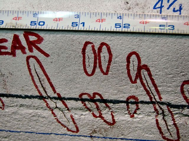
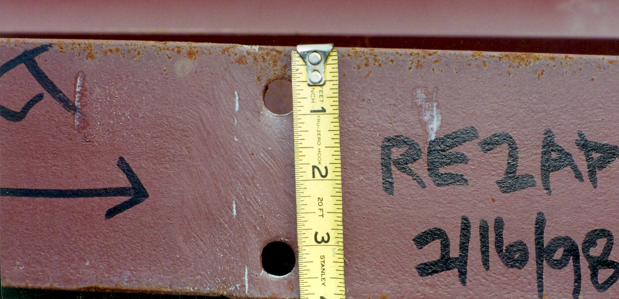
It appears that it did work, so here's the good part. All the components are positioned in the vertical so that excess powder fell off and I didn't have to use a squeeze bulb to blow off the excess. The magnetic powder was held in place by the retained magnetic fields. I used direct current in these photos so the indications would remain while I took the photographs. The powder was not held in place by weld geometry. All the powder fell off when the part was demagnetized by slowly removing the energized AC yoke a short distance from the part. In one case the steel was shipped back to the fabricator to be reworked, one case the repairs were made in the field, and in one case all the parts were scrapped and new ones fabricated. All were welded with GMAW.

Best regards - Al
Parent - - By MDG Custom Weld (***) Date 03-01-2007 14:24
Thanks again to all of you for your great detail of the mag inspection process.  I do have one comment about overlap.  As was discussed the process used was GMAW-S, which we all know is prone to overlap, or lack of toe fusion.  We do many daily cut and etch samples, most of which are on weldments fabricated to no specific standard or code.  We look primarily at the leg length and throat, and if we have the required size on each, we allow some overlap to be present.  The mag inspection process would identify this as an area of concern and require further inspection if the contracts dictated as such.  Should our inspection criteria be questioned for allowing some overlap, or would the c/e samples be enough to stand by?  I have yet to get the parts in question delivered to see if the welds that failed are covered by our PQR and have c/e samples to dispute the mag inspection results showing the lack of fusion.
Thanks,
Mark
Parent - By 803056 (*****) Date 03-01-2007 16:20 Edited 03-01-2007 16:36
In my humble opinion, if your client does not include a reference to a specific welding standard, you can pretty well do as you please. However, that being said, you have to consider your company's reputation and the consequences of legal action taken by your customer should something fail in service.

One of the advantages of adopting a nationally recognized welding standard as your company's standard (for work that isn't covered by an different standard) is that it can improve your chances of weathering legal action should one of your weldments fail in service. An national standard that meets ANSI requirements is developed by committees that are considered to be "experts" in their field and represent a balance of end users, manufacturers, suppliers, etc. National standards can usually be shown to have long histories of successful use and are revised periodically to include the "lessons learned" by the industry. You make your position easier to defend if you can show that your welds met the requirements of the nationally recognized welding standard.

The alternative is to develop your own in-house welding standard that may be difficult to defend without extensive and expensive development programs. For example, you mention you allow some overlap. Were you to develop your own in-house standard, the questions I would ask would include; "how much overlap is allowed and is any consideration given to the type of loading, i.e., static versus dynamic loading?" "Do you have any research or test data to support your position?"

Part of my practice is developing in-house welding standards with my clients. We consider the type of work being performed and then adopt a national welding standard and in some cases tighten up on the acceptance criteria in consideration of the specifics of the project(s). For example, one of my clients builts components for the power industry. ASME Section 1 and B31.1 are typically referenced by the project specifications. The undercut allowances per B31.1 (1/32 inch) is nearly as great as the wall thickness of the tubing they are fabricating. Needless to say, we reduce the allowable undercut to 10% of the wall thickness, which is to say none is permitted considering the tubing is only 0.035 inch thick. We never "loosen" the acceptance criteria.

Only you can say what is reasonable for the work you do. I do urge you to consider the type of welding you do and the industries you work with. Is there one or two industry standards, i.e., AWS D1.1, D17.1, API 1104, ASME SEction VIII, etc. that applies to the majority of your work? If so, consider adopting the welding standard that applies to the majority of your work as your in-house standard and apply it to all "non-code" work. You can tweak the acceptance criteria to meet your needs, but do not loosen the acceptance criteria beyond those provided by the welding standard you elect to adopt.

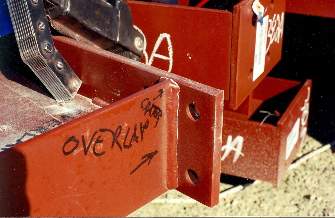
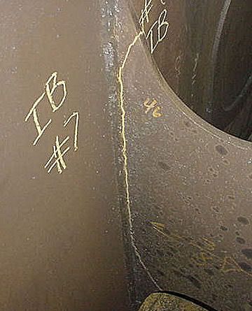
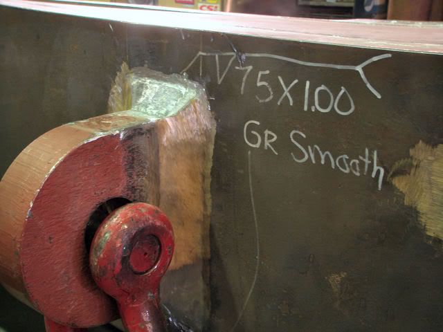
Last word: I have attached a photograph of a failed machine part. As can be seen in the following photo, overlap was observed and marked out by another inspector after the initial failure occured. However, the machine was never inspected or subject to NDT by my client and no national welding standard was referenced in the project specification. My client accepted the delivery of the machine without any inspection other than that performed by the manufacturer. Over time, a crack, originating at the overlap, developed and propagated through the plate and now the part has to be replaced. The replacement part is $30,000 not including the cost of installing it and the cost of the lost production time involved. As is usually the case, I was called in after the failure occured. How bad was the overlap? "Not that bad" according to the manufacturer. It is interesting that the remaining length of weld doesn't have any overlap and has not cracked.

Good luck - Al
Parent - - By thirdeye (***) Date 03-01-2007 18:06
Al,

Thanks for posting those pictures, the indications speak for themselves. Just goes to show how important the toes of a weld really are.  BTW, is de-mag called for in the procedure, or just a shop practice?

Here are a couple from my collection.  These are 3/8" fillet welds.


More and more, smooth ground fillets with a slight grinding of the toes are being called out, not just on lift lugs like this but for a few inches at the termination of gussets or high stress areas.

Parent - - By 803056 (*****) Date 03-02-2007 02:25 Edited 03-02-2007 02:28
I do believe AWS has hit a home run with the added ability to attach photos to our posts.

I typically demag after doing the magnetic particle test with DC just in case someone has to make a repair weld. There are few things that can drive a welder crazy like arc blow due to a remant magnetic field. Even with AC, after I break the initial contact, I typically remove the yoke with the power on and twist the yoke as I move further away. I find that demaging parts on which the welder has done a lot of grinding or, in some cases, machining is beneficial.

By the way Thirdeye, good photos.

Best regards - Al
Parent - By ross (***) Date 03-02-2007 20:06
Al said: "I do believe AWS has hit a home run with the added ability to attach photos to our posts."

Thanks, Al. You guys make the forum worthwhile. Whatever you need, let us know.

Ross
AWS Marketing
Parent - - By NDTIII (***) Date 03-03-2007 04:52 Edited 03-03-2007 05:35
Al, of course I recall that. However, that was a long long time ago and many many many many many..........many Mag Particle examinations ago. But let me explain something to you.  Yes you can show a magnetic field on a pice of wood with a yoke. I don't care how thick the paper is, because that only shows you the direction of the magnetic field, not the strength. Since a pie gauge does not tell you the strength of a field with a yoke either (only direction), you must depend on a 10 lb. lift to demonstrate your field strength. That is the best we can hope for.

I still say you must demonstrate the procedure before I would accept it. Color contrast paint is thin and it has been proven to allow indications to be seen easier than without. That is a different issue.
I am not saying you can't. I'm only saying prove that you can.

One question for you. The picture you attached. Is that actually showing the Magnetic Particle indication of the crack or is that chalk or soapstone being used to highlight the flaw? It doesn't look like particles to me. It looks like chalk or soapstone.

One more thing; There is also a big difference between the flux leakage from a gaping crack and over lap and the flux leakage from Lack of Fusion. Again I say prove it before you do it.
Parent - - By 803056 (*****) Date 03-04-2007 03:33
My photos are of the actual indications produced on materials with shop applied paint.

Let's not mix the requirements of a code or NDT standard imposed by a customer with performing a simple preliminary test to gather information about what's going on with a weld or any other component you with to examine. I agree with you that if I'm testing a part in accordance with a code that imposes the 10 pound lift, but I disagree if there is no code or standard imposed. That's like saying you can't evaluate a weld visually because the intensity of the white light at the test surface is less than 200 ftcd. It's only true that I can't visually inspect the weld per ASME Section V. There are no intensity requirements stated in AWS D1.1.

I believe the photos I included with my post says it all.

Best regards - Al
Parent - By thirdeye (***) Date 03-04-2007 16:38
Al,

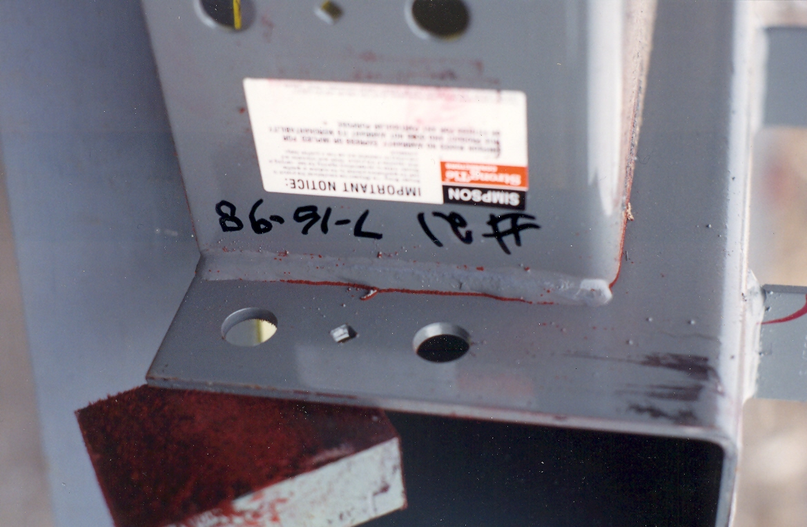
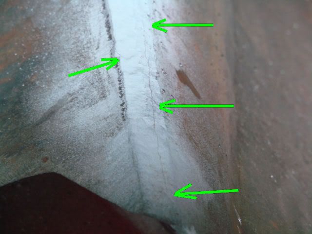
Lets also not overlook residual magnetism.  I can't tell you how many times indications are seen because they collect grinding dust from the shop floor.  In this picture, it is not possible to get a yoke inside this compartment.  The plate is 5" thick, so even using prods from the outside face is not effective.  I just reach in and dust with yellow powder. Then inspect with a mirror.  The cracks usually begin in the area of the 1" square backing bar, but this one has migrated into the plate as well.  During the preliminary walk through of a power shovel, dragline or other earth moving equipment I always take a powder blower for this reason.


The same with this crack.  The contrast paint used following repair 18 months earlier was still present.  I reached in and dusted this joint through a 4" inspection hole at a distance of 30".  Using an air wand with a valve to reduce the flow, the powder is gently blown away to reveal the crack.

Parent - - By CWI555 (*****) Date 03-04-2007 17:29 Edited 03-04-2007 17:33
I have to agree with the prove it idea. To thick a coating will adversely affect the test. I've been interested in following this, I've noted somethings that do not appear right to me, here is a short list of them.

1. Quote "I often use MT with an AC yoke in the field as a means of confirming overlap conditions and other deleterious conditions in steel materials that can be concealed by paint."I would not call this a true MT indication, it would be formed from the geometric configuration of the cold lap as compared to the flux leakage type indication as depicted by a crack or porosity hole. I've retrained Level II's who tried to sell me on that idea. knowing the difference between a flux leakage indication and a geometric indication is an absolute requirement for a qualified Level II inspector.

2. The AC yoke that you quoted should not be leaving any measurable residual magnetic field in the material. I can understand if you had said DC, but given typical structural material (A36, A572 etc) is typically Low retentivity and high permeability and thus the reason for using MT to begin with. I can see it in a position such as flat and in some cases where surface tension of a coating or other factor would hold the powder (which btw would itself call into question the results of the test as the powders need the ability to move, and anything that interferes with that interferes with the test), but I seriously doubt the piece is retentive to the degree described. I suggest the use of a Gauss meter to dispel the notion of retained magnetic field.

3. It would be a cold day in hell before I signed off on an MT report performed through a thick coating if a reference block with the same mils of the same coating with a known flaw was not used. That would be the only way the results could be considered validated.

In short, I would definitively call bull#### on any report of that nature that came across my desk unless it had the supporting data as noted above.
Parent - By NDTIII (***) Date 03-05-2007 09:45
Thank you..
Parent - - By 803056 (*****) Date 03-05-2007 13:30
Please reread the post. I stated that the MT was performed with a DC yoke and demagnetized with AC yoke (same yoke with AC/DC capability).

There is a difference between thick paint composed of several layers and shop paint. Shop paint is usually applied as a single application and is rather thin.

If you doubt the affects or existence of a remnant field, talk to a welder. They have an appreciation for the affects of residual fields and the strength of remnant magnetic fields in low carbon and low alloy steels. Grinding and machining can also produce weak residual magnetic fields that will retain magnetic powders in the areas of cracks, incomplete fusion, etc.

To my recollection surface tension is a characteristic associated with liquids, not dry films. As I said, the testing was performed with the plates in the vertical positions. All the powder would fall away when the AC yoke was removed. DC was used to produce a residual field so I could photograph the indications. Were the indications as strong and long as those produced with the magnetic yoke energized? No, but it allowed me to photograph the problem areas and show the client what needed to be addressed. The powder fell away once the part was demagnetized using the AC yoke.

If the MT was being performed in accordance with a code or standard that requires the procedure to be qualified as is the case with aerospace applications, military standards, etc. the procedure has to be qualified.  However, there are many instances where product isn't accepted or rejected on the basis on a single NDT method. The NDT is simply one of many tools used to quickly decide what course of action is necessary to better evaluate the material.

The bottom line is that indications formed as a result of remnant field or by the use of an AC or DC yoke or prods can't be discounted simply because someone doesn't like the fact that there was or wasn't paint present or that the procedure was or wasn't qualified per some standard. The indications were formed by flux leakages that resulted from the presence of weld discontinuities that were later confirmed by additional testing and exploration. The MT performed as intended in an imperfect world.

Best regards - Al
Parent - - By CWI555 (*****) Date 03-06-2007 04:20 Edited 03-06-2007 04:45
A few quotes for context and relevance first:

From NDTIII

"Not with an AC Yoke you won't. I'll take that bet. Just how much do you have to lose?
You still have to demonstrate it before you do the examination. You can't just perform it through paint. "

Your reply was

"I use the continuous current, dry particle technique with an AC yoke to check weldments that have shop coat paint on a regular basis"
and in another post
"I often use MT with an AC yoke in the field as a means of confirming overlap conditions and other deleterious conditions in steel materials that can be concealed by paint."

and in a later post in which you posted pictures, was the first reference to DC

"All the powder fell off when the part was demagnetized by slowly removing the energized AC yoke a short distance from the part."

There was no reference in this to AC/DC yoke. You clearly stated "AC yoke" However at the beginning you stated continuous current which is a term for DC. This was a contradiction, you said nothing in that segment in regards to AC, it was only when you had posted pictures that the comment first came out. ( I re-read them all)

for context, the original post was in regards to a thick paint, and had nothing to do with "shop paint"

From MDG custom weld:
" just got a call from a customer that fabricated some pallet transfer stations for an automotive plant.  A few of the welds failed in the field, and the auto plant brought in a third party to mag partical test the rest of the transfer stations.  They sent me some pics of the parts they tested that were labled as "suspect" for lack of fusion.  All of these parts are painted with a thick industrial enamal paint. "

Shop paint never came into the picture until you mentioned it.

Then from your last post:

"If you doubt the affects or existence of a remnant field, talk to a welder. They have an appreciation for the affects of residual fields and the strength of remnant magnetic fields in low carbon and low alloy steels. Grinding and machining can also produce weak residual magnetic fields that will retain magnetic powders in the areas of cracks, incomplete fusion, etc."

I have a better than average understanding of it. Your comment implies that I do not. I fully understand the causes, and probably a few you've never thought of. I have enough welding experience, Coil shot MT, head shot MT, Prods (Let us not forget the magnetic rubber method for internal threads among others) EMAT, MFL and ET experience to understand such things as magnetic arc blow, residual fields, hysteresis loops etc. your comment in this regards I took as highly condescending. I suggest in the future you try to understand a little bit more as to whom your speaking with before you treat them as ignorant.

As for surface tension I offer the following.

http://en.wikipedia.org/wiki/Surface_tension

Please read it in full, and re-read my post in context.

NDTIII gave you solid advice, I suggest you take it.

If I am still ignorant in your eyes, well there isn't much I can say to that.
Parent - - By NDTIII (***) Date 03-06-2007 04:27 Edited 03-06-2007 04:33
Excellent CWI555! I see you've done your homework.

I myself have done more than my fair share of MT examinations in the past 30 years.

I do not want people in this forum or other forums telling people it is OK to perform MT through  paint without demonstrating it first. These kind of postings make our lives difficult.

"Well I saw on AWS that I could". Well you can't, unless you prove to me that you can!

Ask a welder what he does to minimize the effects of magnetizm on pipe. I've seen many pipes that were magnetized enough to hold electrodes. You wrap a welding cable in the form of a coil around the pipe and pump AC current through it.
Parent - - By CWI555 (*****) Date 03-06-2007 04:42
[deleted]
Parent - - By 803056 (*****) Date 03-06-2007 05:47
As an old friend says, "You can lead a horse to water, but you can't make it wear a bikini."

I will concede that I used an incorrect term. I used the term "continuous current" instead of "continuous method". I apologize if that threw you.

I did follow your thread on surface tension and read the definition they provided. It refers to the surface tension of liquids. What point am I missing?

It sounds like you might do a lot of work in a testing lab and have a different prospective than I do. 95% of my work is in the field where every job is somewhat unique and I am performing NDT to gather information, not necessarily to accept or reject parts. It sounds like you are working to a NDT standard(s), where as most of my work isn't covered by a standard. If you work in a lab, you have the luxury of working with clean conditions and with clean parts. I'm usually working in grease and oil up to my elbows and I'm lucky if the equipment has been power washed. Rarely is the owner going to remove paint for either UT or MT before the initial round of testing.

You seem intent on reading into my post more than is stated. I stated the facts and never have I said that there are no upper limits to the thickness of paint. Clearly there is. I never said that I can detect the smallest of discontinuities, increased paint thickness will surely degrade the sensitivity of the MT method. My position is that you can't discount the indications that are produced and they (the indications) are typically due to discontinuities that are present beneath the paint. The photographs I included in my post showed the indications that formed on three different projects and it provided the justification needed by the owners to do additional testing. 

I apologize if I touched upon a raw nerve. It isn't my intention to get you upset just because I disagree with you. I attempted to use some logic to add credence to my position. If you don't agree, so be it. It's our differences in opinion that keeps the forum interesting.

I stand by my original position that just because the MT was performed on a painted surface, the indications reported can't be discounted. As stated in my previous post, I believe the initial report listing the results of the magnetic particle tests provides the owner with the justification to do additional testing and exploration to determine the cause of the failures. Was the original welding the problem? We did learn in a later post that the welds were made with GMAW-S (prone to fusion type defects). Was it a design problem? We can suspect the design is the problem if the welds are discovered to be the required size and are sound. I guess we'll have to wait and hope we hear from the fabricator that is doing the repairs.

This horse has been beat long enough.

Best regards - Al
Parent - - By NDTIII (***) Date 03-06-2007 06:32 Edited 03-06-2007 06:53
I work in the field as well and I still say you don't perform MT through paint unless you prove it first. Especially with a yoke!
You implied that it was ok. Well I'm sorry but it's not.

You said:
"I am usually working in grease and oil up to my elbows and I'm lucky if the equipment has been power washed. Rarely is the owner going to remove paint for either UT or MT before the initial round of testing." 

What kind of results are you looking for? What kind of NDT are you doing? What kind of an outfit are you working for? That makes no sense to me. I hope this equipment cannot fail and hurt someone, because I can almost guarantee you will miss defects with the conditions you are describing.  I am just really confused now as to what type of industry or workplace you are working in. The more you talk the more I am wondering. What do you mean by "intiaial round of testing"?

You also said:
I used the term "continuous current" instead of "continuous method".

Ok, maybe I am ignorant. What is the difference? The continuous method of magnetization means leaving the current on while magnetic particles are applied. Even I remember that from school.

You are right on one thing though. This horse is dead.........................

Have a nice day and whatever you do, do not take any of this personal. Because it's not!
Parent - - By MDG Custom Weld (***) Date 03-06-2007 19:25
As you all have shown many different ideas and opinions on the accuracy of going through paint, I thank all of you for your input. 

I just received confirmation that I will not see the parts that failed, or any of the parts that were suspect.  My customer is stuck trying to make the right decision on accepting responsibility for the failed parts.  I have given my professional recommendations that they do not agree to any responsibility until they are given parts that failed to inspect and make further determinations as to the failure mode.

I have also verified that the joint is a partial pen, with the root in tension, loaded cyclically.  The load is 50 lbs at a 36" distance 90 degrees to the weld face.  As you ME's can calculate, this is a big moment applied to a 24" span with 1" welds on 6" centers.  I don't think it's a question of "if". It's now a question of "when".

This just keeps getting more and uglier as each company tries to pass the buck!!
Parent - - By NDTIII (***) Date 03-07-2007 04:28
Well good luck and keep us posted.
Up Topic Welding Industry / Inspection & Qualification / Mag partical testing over paint
1 2 Previous Next  

Powered by mwForum 2.29.2 © 1999-2013 Markus Wichitill