Not logged inAmerican Welding Society Forum
Forum AWS Website Help Search Login
Up Topic Welding Industry / Inspection & Qualification / AWS D1.1 Table 6.3
- - By samchiu Date 06-19-2007 03:40
Could anyone please teach me about Table 6.3 in AWS D1.1?
1. what are the numbers (db) represent?
2. say, if there is a flaw in a 80 mm thick butt weldment at 25 mm down from the surface, how can I work out the sound path using a 70 degree angle beam? Would I get the same db if the identical flaw is in a 120 mm thick butt wledment at 25 mm down from the surface?
Thank you very much.
Best regards,
sam
Parent - - By CWI555 (*****) Date 06-19-2007 04:37
Most of what your asking is basic UT inspection.

1. db = decibels. decibels as defined by asme is twenty times the base ten logarithm of the ratio of two ultrasonic signal amplitudes db = 20 log10 (amplitude ratio)
amplitude is defined as the vertical pulse height of a signal, usually base to peak, when indicated by an A scan presentation.
In short it's a measure of energy, both in amount of return, and amount initially probagated. Low amplitude is to a whisper, what high amplitude is to a shout. 10 db vs 20db. etc.

Using your flaw example: the smaller the flaw, the less energy/decibels that are reflected. The larger the flaw, more energy/decibels reflected for a given angle.

2. all other factors remaining the same (material, angles etc) a 25mm deep flaw in an 80mm thick butt weldment, will reflect the same as the same exact flaw size and dimension 25mm down in a 120mm thick weld.

depth/cos70 = metalpath/soundpath 73.095mm sound path for a 25mm deep flaw.
inversly
soundpath*cos70 = depth.

A few basic formula:
depth x tan of the angle = surface distance
depth/cos = metal path
metalpath x cos = depth
metal path x sin = surface distance
surface distance / tan = depth
surface distance /sin = metal path
Parent - - By samchiu Date 06-19-2007 12:40
Thank you CWI555.
So, for the same flaw size at the same location within two different thickness weldments would give the same db reading. Then,
1. Does Table 6.3 mean that a thin weld would allow only a small flaw but a thicker weld would allow a larger flaw?
2. Is there a relationship/formula I can use to convert the db values (in Table 6.3) into flaw size? Or, how do I obtain the size of the flaw?
3. Since db = 20 log10 (amplitude ratio), would the size of the D50 mm hole on the IIW block be used as a reference flaw size? (by checking figure 6.21-24, it seems like that angle transducers are calibrated using the D50 mm hole)

Sorry to draw up so many questions. Thank you for all the helps.
Best regards,
sam
Parent - - By jwright650 (*****) Date 06-19-2007 12:59
Sam,
Looking at your question #1....I think the reason the Chart allows larger reflectors in the thicker materials is because they would not be as detrimental to the weld as if they were present in the thinner material. <---not sure that makes sense, but that is how I was looking at it.
Question #2, the flaw's physical size may not be representative of it's reflection, due to the orientation/reflectability/shape...ect of the flaw.
Question #3, you set your sensitivity on the side drilled hole, and that calibrates the whole UT machine, cables, tranducer, wedge, coupling between the wedge and transducer....etc...it gives you a standard to work from, so that when another inspector looks at this joint he/she will find exactly the same indication/reading as you did because you both used the same sized reflector to set up your machine.
Parent - - By samchiu Date 06-20-2007 01:08
Thank you John.
Parent - - By samchiu Date 06-20-2007 02:18 Edited 06-20-2007 22:53
sorry, more questions.

1. say, if there is a flaw resluts a final db value of +3 (using a-b-c), could the +3 db indicate the shape (eg. big hole, small hole, narrow crack, etc) of the flaw?
2. Waht does the +3 indicate in terms of the reference hole on the IIW test block?
3. Is section K10 (in annex K) the only way to obtain the type of discontinuity?

many thanks.
Best regards,
sam
Parent - - By jwright650 (*****) Date 06-20-2007 12:01
Sam,
For answer to your question #1 look back at my answer to your last question #2.
Question #2, the reference hole is only a "standard" to set your machine to, so that all inspectors will be working with the same relative sensitivity and won't be arguing over whether an indication is acceptable or rejectable per the Table.
Question #3, I dunno, you lost me with that one....Annex K is a list of definitions. However, I'll take a stab at what I think you are trying to get at. Signals that you see on your UT screen will have signatures, at times these signature are very representative to the type of flaw that you have found and you can determine by the signature and the cordinates of the flaw within the joint, exactly what type of flaw you have found. Other times, it is purely a shot in the dark and and a wild guess and the only way to find out what it is you have found to to go in after it with the back gouger. With experience, the signatures will make more sense. Knowledge of the type of joint prep, and conditions before welding will also help you determine what you are seeing on the screen. For instance, a cluster of porosity will have a distinct signature that probably any in-experienced UT tech will see right away and know what it is they have found. Other signatures may take more experience to figure out, other signatures...nobody will know.
Parent - - By samchiu Date 06-20-2007 22:56
Thank you very much, John. Thank you for taking time in explaining things well to me.
Parent - - By samchiu Date 06-25-2007 23:22
Could someone post me some diagrams on the UT screen, please? Some examples such as the calibration reading for the IIW block and flaws ... Many thanks. my E-mail address:
chiu_hs@hotmail.com

Best regards,
sam
Parent - - By samchiu Date 06-26-2007 00:26
Could anyone help please? how did AWS generate the 'acceptance-rejection criteria'? is there any books written based on the ceriteria? Thank you very much!

Best regards,
sam
Parent - By Joseph P. Kane (****) Date 06-26-2007 11:28 Edited 06-26-2007 11:30
Why do YOU want to know that?  The start of your string indicates that you are not really a practicing technician in UT.

Reportedly, t was based on scientific research by Mr George Schennefeld, P.E., phD. in collaboration with Mr. Warren Alexander, P.E., then presented to the cognizant  D1.1 Subcommittee.  It took into consideration some Fracture Mechanics, refined it and then got it adopted into the Code.
Parent - By jwright650 (*****) Date 06-26-2007 12:04
Hi sam,
I would really like to help you become a sufficient UT tech, but to gain the instruction to do a simple calibration to an IIW block that you are looking for, you really need some formal classroom training under a qualified Level III instructor. It would be very impractical to try and teach the UT method completely over the internet in a forum such as this. According to the ASNT's recommended practice SNT-TC-1A, there are education/experience prerequisite requirements and minimums of classroom and practical instruction to become a working level UT techinician(level II). Most of your questions will be covered in the first or second classroom sitting of the Level I UT instructional program.
Parent - By thirdeye (***) Date 06-26-2007 14:22
Good morning Sam,

I don't mean to butt in here but I would like to recommend a book to you. "Ultrasonic Flaw Detection for Technicians" by J.C. Drury.  It has been around since the 1980's and is now in it's 3rd edition.  It is one of the  benchmark reference books most UT technicians have in their library.  I think you may find it interesting. You can order it here.  Delivery is very prompt.  Maybe others will comment on this book as well.

http://www.silverwinguk.com/en/ultrasonic_flaw_detection_jdrury.htm

Unit 6 Kingsway Business Centre,
Swansea West Industrial Park,
Swansea SA5 4DL,
Wales UK.

Tel: +44 (0) 1792 585533 Fax: +44 (0) 1792 586044

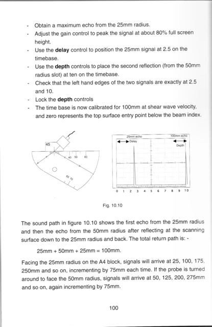
Here is an example of the content in the calibration chapter. This page is discussing timebase calibration using the A4 (DSC) calibration block.  There is also information on using the IIW block but it is spread over several pages.  This should give you an idea of what to expect in this book.


~thirdeye~
Parent - - By Joseph P. Kane (****) Date 06-26-2007 18:39
I would suggest that you try to get a set of Week 1 and Week 2 of the Krautkrammer text books that you get when you go to their two week course.  (Level 1 and Level 2)  These books have basic instruction and examples and homework lessons.  However, Jim Wright is right.  From the flavor of your questions, you need some basic schooling under a UT Instructor.  If you are using UT for D 1.1, or any D1 Code, you also need specific and practical examinations to the requirements of these codes in addition to the ASNT SNT-TC 1A  requirements.
Parent - - By CWI555 (*****) Date 06-26-2007 20:17
"you also need specific and practical examinations to the requirements of these codes in addition to the ASNT SNT-TC 1A  requirements. "

Far to many people skip over the last sentence of para. 6.21 D1.1. Very good point.

Regards,
Gerald
Parent - By samchiu Date 06-27-2007 00:44
Thank you all for the thoughtful replies. No, I am not a practicing technician yet. I thought I should know some fundamental principles before I take the UT inspection class. Well, it looks like that the principles are covered in the first lessons. again, thank you all for the helps. I am very glad to know that there are some many experienced good persons here. Thank you!!!

Best wishes to you all.
sam
Up Topic Welding Industry / Inspection & Qualification / AWS D1.1 Table 6.3

Powered by mwForum 2.29.2 © 1999-2013 Markus Wichitill