Not logged inAmerican Welding Society Forum
Forum AWS Website Help Search Login
Up Topic Welding Industry / Technical Discussions / Odd visual condition of Haynes 188
- - By Ringo (***) Date 01-31-2008 11:52
We are trying to certify a qualify a WPS with Haynes 188.The filler material is Haynes 188,.062 thick,manual GTAW (no pulse),argon shielding.The problem is the way the deposited weld bead looks,in that,is it as if there is a separation of the alloy in the weld metal.The center of the bead is a gold/straw type of color,and the on the sides is a grey mate looking color almost like a slag.I looked at it under a stereo microscope,and its all tied-in good,but looks as if there is some type of segregation.

We have done all the basic stuff (prep,heat input,etc.),and I even welded a test coupon myself and got the same condition.

Has anyone seen this condition?is it acceptable?We send the test plates to Arizona for X-ray,which is a bit expensive,and I do the visual before they are sent.

Any help?

Thanks,Ringo 
Parent - - By ssbn727 (*****) Date 01-31-2008 14:07
Hi Ringo!

It would be most helpful for us and yourself to post a picture of the weld in question in order to give you a better opinion of what you're describing.
Also, if you can post a pic of what you observed through the microscope, would also be beneficial for a better opinion.

Respectfully,
Henry
Parent - - By Ringo (***) Date 01-31-2008 17:47
What is the best way to post a picture?
Attachment: MVC-434S.JPG (39k)
Parent - - By Lawrence (*****) Date 01-31-2008 18:24 Edited 01-31-2008 18:34
Ringo,

All I can say is that you are looking at what can be typical for Haynes 188.

These "edge oxides" were considered typical by our process engineers and acceptable by inspectors.  I really wish I would have asked deeper questions about the "Why's" of your phenomina. They told us that quite often in hot section refurbishment work that those oxides were desirable for performanc reasons.

I've experienced exactly what your talking about with Haynes 188.  I've also seen wierdness with Rene 41 when it is used to hardface over Inco 718.

The whole purpose of Haynes 188 is high temp service that is subject to high air flow or other cyclic or frictional forces, Hence the Cobalt and Tungsten (it's a true superalloy)... What keeps this stuff from corroding/degrading in service, is that it makes it's own powerful oxide that is super tenatious. I think this is what you seeing on your weld edges..... This is from memory and speculation and not anything to bank on... But I bet your samples do fine at the lab.

I have also known folks to use 2 1/2 % Hy in the shield gas (both GTAW and Micro-Plasma) to provide better wetting at the edges and faster travel speeds in production.  I don't know if the Hy would have an effect on the surface appearence... or again, if that surface appearence is anything to be worried about in the first place.

What is acceptable is still determined by the criteria of what ever code you are subject to as well as contour and airflow limitations provided by your engineers.

However, I bet I could make that phenomina go away with an Aerowave or a Dynasty 350...  :)
Parent - - By Ringo (***) Date 01-31-2008 18:52
Thanks Lawrence

I've been told some of the same things that you spoke of by other CWI's,Welding Engineers,Etc.,but I figured with all the welding knowledge here I would get some good advice.

By the way, this was welded with a Miller Dynasty 350.
Parent - - By Lawrence (*****) Date 01-31-2008 19:09
Ok Ringo Here is my very own seceret recipie.......  I'm in negotiations to sell it to Col Sanders at NASA so don't tell a soul about the 13 special ingredients.

Try  alternating current.

Assuming square groove butt weld 0.063 sheet with no gap and argon backing.

Sharpen a 1/16 Cerium (orange) electrode with a very tiny blunt at the end.  Not a long slim taper but a rather radical tip prep angle.

400 hz or as fast as your Dynasty will buzz
Balence control 98% EN 2% EP
Amperage 80 EN  150-200 EP

If your tungsten rounds at the tip reduce EP amps by 10 until you get that little puff of etch and keep your electrode pointed (with just a tiny shine at the very tip of your electrode).

This ought to blast off the little bit of oxide that causes the green "aura" around your superalloy... That nasty, sluggish cap that floats on top of your puddle of Haynes 188, inco 901, 718, Has-X etc.

Of course I doubt you will ever be able to get Pratt, GE or CFM to buy in on AC for your procedures... But I bet it will work to remove that oxide at the toes of a test piece or some scrap you have laying around   :)
Parent - By Kix (****) Date 01-31-2008 19:26 Edited 01-31-2008 20:33
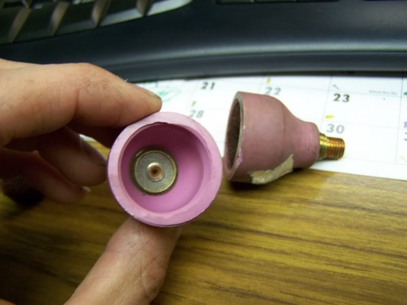
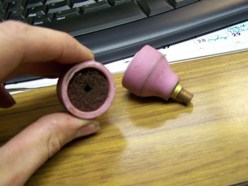
Try slowing it down a bit with less amps and give the puddle time to boil through the backside instead of using lots of heat and push to get ya through the back.  This will give you a smaller bead and allow longer gas coverage on the solidifying puddle.  Use a bigger gas lens with more cfh.  This one would get cha a sweet looking bead and pass your test no prob. [IMG]http://i11.photobucket.com/albums/a189/vdubin474/Gaslenses003.jpg[/IMG]  Or you can make one because that one is a bit on the pricey side.  Here's the home made version.  [IMG]http://i11.photobucket.com/albums/a189/vdubin474/Gaslenses007.jpg[/IMG] 
[IMG]http://i11.photobucket.com/albums/a189/vdubin474/Gaslenses002.jpg[/IMG]
Stainless steel wool works better then scotch bright.  Scotch bright only lasts for so long and then you get a hole by the tungsten which causes turbulence.  Although with the amperage you should be running at, the tungsten shouldn't get hot enough to make a hole.
Parent - - By Ringo (***) Date 01-31-2008 20:25
That's a very interesting combination of variables Lawrence.I never would have thought of using A/C,and your right in that Rolls-Royce would never buy into it,but I will try it.Also,I have never used the orange tipped tungsten on the Dynasty,because it has the warning on top to use only 2% thoriated.

Thanks for all your help,
Ringo
Parent - - By Lawrence (*****) Date 01-31-2008 21:28 Edited 01-31-2008 21:36
Awsome Ringo,

If it works send pictures....... and er... even if it doesn't I suppose

If your not going to use crazy Asymetric wave forms the whole notion of the Aerowave/Dynasty 350 is wasted.

With just a little tweaking those parameters can dig real deep into heavy sections of aluminum with a pointed electrode.  The extended balence control with these new inverters is really a waste of time without the ability to control amplitude each half cycle in my opinion.  With that control a whole plethora of ideas become possible.
Parent - - By Ringo (***) Date 02-01-2008 18:23
Lawrence

We haven't used the square wave as we should on that machine (Miller Dynasty 350),and the reason we got it was for the aluminum capability.We test to AWS D17.1,and per figure 4.12B,the testing facility fails any burn thru on the back side of the tee-joint.We use .040 tungsten,.060 thickness on the plates,and fuse the first pass,then add wire.I can't say I totally agree with their interpretation,but they are the ones making the call.Any help would be appreciated,you seem to know your stuff.

Thanks,
Ringo  
Parent - - By Lawrence (*****) Date 02-01-2008 19:35 Edited 02-01-2008 19:37
Ringo,

I'm looking at Figure 4.12B-Incomplete Fusion at Root in Fillet welds when the thickness of any member is less than or equal to 0.063.

It describes allowable limites for incomplete fusion at the root of fillet welds. 

Figure 4.12B shows no burn or melt thru on the back side of Tee joints nor does the associated text speak to burn thru on Tee joints.   If they are using this figure to bust welds with discontinuities on the back of the Tee's they are using the wrong text to back themselves.

Still they are prolly making a righteous judgement...
I think you want to turn your attention the limits found in table 6.1 for undercut/underfull and /or Concavity. They are quite strict and would seem to apply to melt thru on the back side of a thin Tee joint that caused a change in the surface of the base metal.  You will notice that a Class A weld gets only 0.005 in depth and 0.020  length (accumulated) for any 3 inches of weld. (that ain't much)

I really dislike the notion of running an autogenous fusion pass and then adding wire on thin Tees. It's bad enough if it's only a trick to pass the test, but you are opening pandoras box doing things like that in production. The number of things that can be affected are just too long to list....

There is no rule against building a fixture that provides a solid heat sink for your Tee Joints.  With a solid and consistant heat sink you ought to be able to make Tee joint fillets in material well below 0.063 without causing any discontinuities on the back side of the parent mateiral.
Parent - - By Ringo (***) Date 02-01-2008 20:54 Edited 02-01-2008 21:05
Lawrence

I think your right in your interpretation of the code,and this must be why they are rejecting our tee joints.I never send any out with any melt thru at all since they reject them.

I also agree that an autogenous pass isn't a good practice,in that the fusion pass usually has transverse cracks,which they tell me they weld over (not good).The testing facility takes a cross section and polishes it,then do their inspection.

I will try your heat sink idea,right now they use those old test plate fixtures for set up.
Parent - By Tommyjoking (****) Date 02-02-2008 07:30
This is pretty interesting post to say the least.....

Ringo I do want to say we are pulling .063 and  fillets single pass with no burn thru  or suckback with manual GTAW....  We use copper sinks always to do this and have our settings down to a religion...   Typical setup is 1/16 thoriated for us with a #4 or #6 cup depending on the access.  I could not do it with a .040 tungsten as it would not hold up to the heat range. 

"edge oxides"  Thank you Lawrence now I know what to call that crap!!!  Thats like a "third finger" moment for me eh?  Is the suppose to reinforce the toes, stop edge cracking or ????  no inverters here...you peak my interest more and more ....

Best Regards
Tommy
Parent - - By Fredspoppy (**) Date 02-02-2008 12:14
Just a quick question here.  Is this joint welded from both sides, or only one?  The photo looks like "suck back" that could be seen during welding of the second side.
Parent - By Ringo (***) Date 02-05-2008 13:16
welded from one side fred.
Up Topic Welding Industry / Technical Discussions / Odd visual condition of Haynes 188

Powered by mwForum 2.29.2 © 1999-2013 Markus Wichitill