Not logged inAmerican Welding Society Forum
Forum AWS Website Help Search Login
Up Topic Welding Industry / Inspection & Qualification / MT Acceptance Criteria?
- - By tom cooper (**) Date 10-30-2008 14:16
AWS D1.1 paragraph 6.14.4 for MT inspection acceptance criteria refers back to "conformance with Section 6 Part C".
The only other mention for acceptance criteria is in paragraph 6.10 which states that "welds subject to MT....shall be evaluated on the basis of the applicable requirements for visual inspection"; paragraph 6.9 states that visual inspection acceptance criteria is IAW Table 6.1.

This is confusing as Table 6.1 cites flaw sizes that are detectable by visual inpection.

Question: Why would a more sensitive and expensive method of inspection, i.e. MT,  be conducted if flaws are only as defined by visual methods?  Did D1.1 forget to include a different set of criteria for MT acceptance??

Thanks for any insight.
Parent - - By js55 (*****) Date 10-30-2008 14:46
tom,
Gerald or hogan, or some of the others would be the guys to give some precise background on this issue, but we have had some threads on tis very subject. If you do a search you will probably be filled in quite a bit on the background.
They didn't forget.
Parent - - By mroach (**) Date 10-30-2008 14:59
Tom, magnetic particle examination much like liquid penetrant is simply an "enhancement" to the visual examination. The only difference is that magnetic particle will also find sub-surface indications. Anyhow, that's the reason why there is no separate acceptance criteria like ultrasound or radiography.
Parent - - By 3.2 Inspector (***) Date 10-30-2008 15:56
First of all, I am not that familiar with the code in question!
But if you use the VT acceptance criteria for MT.....hmmmm, seems a bit strange to me.

Lets say you do MT on a butt or fillet weld, no indications appears but the weld has undercut or incomplete filling, would you then accept the weld, and use the VT criteria as reference?

In europe each method of NDT has its own acceptance criteria as each method has its limitations.

Maybe I just misunderstand this thread, it has happend before :)

3.2
Parent - - By hogan (****) Date 10-30-2008 16:01
This is a standard requirement for structural steel in the USA. The code additionally requires that welds be found visually acceptable prior to any NDT being performed. Hope that answers your question.
Parent - By 3.2 Inspector (***) Date 10-30-2008 16:14
Yes it does, thanks.

3.2
Parent - By Mikeqc1 (****) Date 10-30-2008 14:58
MY GUESS IS IT'S BECAUSE MT IS A VISUAL ENHANSMENT.
MDK
Parent - - By hogan (****) Date 10-30-2008 15:08
Tom,
As mroach has stated MT, as well as PT, are just enhancements of a visual inspection. Typically these two methods are for the detection of discontinuities open to the surface. An example would be a very tight crack that is open to the surface, but can not be visually detected. When you MT the area the crack will jump out. It is similar to using a magnifying glass or optical comparator to enhance a visual inspection.
Parent - - By thirdeye (***) Date 10-31-2008 11:33
And speaking of enhancement.....when preparing a weld for MT inspection with contrast paint, things like overlaps, undercuts, surface porosity and some cracks show up nicely.  I can't tell you the number of times something was missed during a visual inspection, but noticed immediately during the prep for MT.


~thirdeye~
Parent - By jrw159 (*****) Date 10-31-2008 13:33
Thirdeye,
  Nice example. :-)

jrw159
Parent - - By CWI555 (*****) Date 10-30-2008 20:32 Edited 11-03-2008 12:27
I would advise reading the commentary section of D1.1. There has also been an extensive thread on that same issue as it relates to PT version. Short answer is AWS utilizes the values as given for visual criteria for flaw size, calcs etc are based off that as well. Table 6.1 gives you those values. Any MT or PT method will highlight the indication. In the case of subsurface it won't be much below if at all. Not many codes recognize MT ability to detect subsurface discontinuities.

Magnifying the indication through powder collection or PT bleed out does not change the actual size of the discontinuity either.

My two cents worth,
Gerald
Parent - - By kipman (***) Date 10-31-2008 13:47
Gerald,
Excuse my nitpickiness (is that a word?), but regarding your last line the size of the indication does change with additional powder collection or PT bleed out, but the size of the discontinuity does not.
Mankenberg
Parent - - By Jim12 (**) Date 11-01-2008 17:30
My experience with MT is that the magnififcation as mentioned in previous posts helps to show the true size of the crack, As with just visual inspection you may only identify part of a crack.
Attachment: HT52802.JPG (23k)
Parent - - By thirdeye (***) Date 11-01-2008 23:33 Edited 11-01-2008 23:40
Jim,

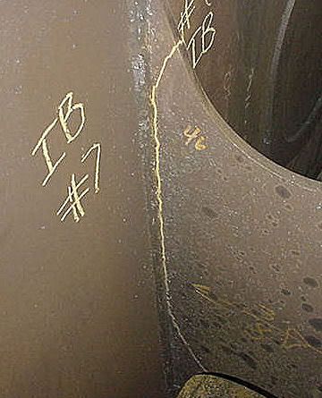
Well if it's magnified, that is not the true size.....but considering the size of magnetic particles, I would think that any accumulation could be considered magnified.   In Kip's post (regarding MT), it sounds to me like he is just pointing out that excessive powder can make an indication appear wider than it actually is.  A perfect example is something we've all seen.... a hairline crack which has been collecting grinding dust in the shop for days.  They almost look like they are growing fur.   This first picture shows a toe and plate crack where, because of limited access, I have to depend on residual magnetism in the part to hold the dust.  These indications are always wider than the actual crack.


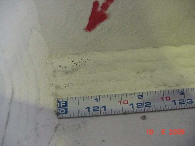
These next cracks on the other hand, are very tight and I used a puffer to blow away the excess dust. They are slightly wider than when you view them under a microscope, but due to the particle size that is the most accurate display I can get unless I switch to wet visible or wet fluorescent particles.


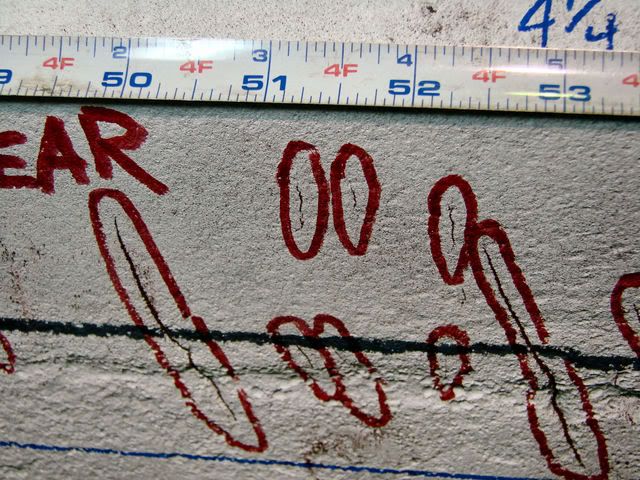
Contrast is something else that works in the inspectors favor, and  that's why I selected yellow dust for the red-iron background and red dust on a contrast painted background.
Parent - - By Jim12 (**) Date 11-02-2008 17:50 Edited 11-02-2008 17:53
sorry for the confusion but what I meant by magnifying, was the length of the crack not how much powder the crk can hold prior to blowing away extra mag powder,with this in mind you may now understand what I was expressing in my original post of "with just visual inspection you may only identify part of a crack" and by magging you can identify almost all of the crack depending on how close to the surface the crack is.Also if you look at the picture I submitted you can see all the crack with mag but prior to MT there appeared to be 2 separate crks.
Parent - - By thirdeye (***) Date 11-02-2008 19:07
Okay, now I got it..... 
Parent - By hogan (****) Date 11-03-2008 15:03
Also with an optical comparator, you have accurate measurements etched on the lens.
Up Topic Welding Industry / Inspection & Qualification / MT Acceptance Criteria?

Powered by mwForum 2.29.2 © 1999-2013 Markus Wichitill