
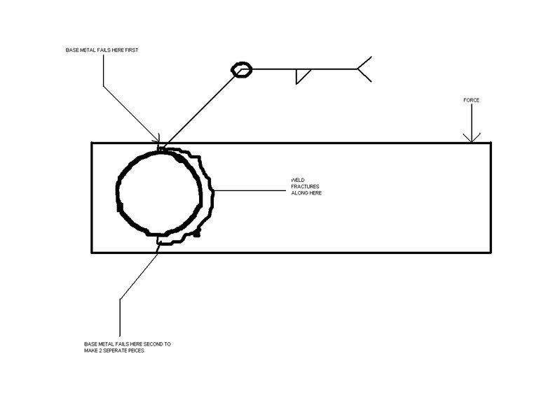
 I was wondering this when I saw this part that was subjected to destructive testing. This picture is a rectangular piece of plate with a hole in it. A 5" piece of pipe slides through the hole very tightly. It gets welded all the way around the pipe. You can see in the picture (hopefully) that the force is exerted downward while the pipe end stays in a fixed position. I marked where the first base material and second base material failures were resulting in the arm falling to the floor.. Now for the question. Did those fillet welds fail in shear the full length of the failure or just some parts of the fillet weld?
You will see by the arrow at the end of the arm that there is a downward force on the arm while the pipe end stays in a fixed position.
This part is made from 6061-T6 aluminum and welded using a 4643 filler with no post weld heat treat. Why the 4643 was chosen in the first place is beyond me. I went to the design engineer and asked if I could switch the filler to the much cheaper 4043 (4043 5.31 a # and 4643 21 dollars+ a #) He said he based his decision off of some chart that had 4643 shear strength at 13.5ksi and 4043 shear strength was 11.5ksi. He told me told me that this fillet weld failed in shear because fillets always fail in shear so we have to keep the same wire. The part withstood 20,000 psi before it failed which is well above what it was designed for according to the engineer. He is afraid that if we change wires that it would fail below 20ksi somewhere and he would loose his 2 to 1 safety factor. I understand where he is coming from, but I don't think he will loose his 2 to 1 safety factor. For one, the welds on the part that failed were absolute Sh!t. No penetration to the root, lack of fusion everywhere and undersized welds.
Thank you Metarinka, you comment was very well understood and well put. The weldment is subjected to a downward force out on the end of the arm. The pipe end is fixed so the arm would have to rotate, but it can't because it's welded together. Your comment says what I was thinking all along, why would you base the strength of your part off of the shear strength of your filler metal in a fillet weld. Especially on one that is best for post weld heat treating. The weld failed because the base material area at the top of the pipe was to small. That let go and then the weld ripped around the scribly side of the pipe. The design engineer has increased that area on top of the pipe now and I want to change the filler.;-)
But do you agree with the change in filler. That's my question. We know the base material failed in tension at the top of the pipe. Directly below the material failure the fillet weld failed in shear for an inch or two and the rest failed in tension. Now that we know how the thing is going to fail in real life and that the base material area of the plate that failed has increased, can we change the filler? Keep in mind that I had higher tensile pulls with the 4043 then I did with the 4643 in the as welded condition.
Al,
I was wondering this when I saw this part that was subjected to destructive testing. This picture is a rectangular piece of plate with a hole in it. A 5" piece of pipe slides through the hole very tightly. It gets welded all the way around the pipe. You can see in the picture (hopefully) that the force is exerted downward while the pipe end stays in a fixed position. I marked where the first base material and second base material failures were resulting in the arm falling to the floor.. Now for the question. Did those fillet welds fail in shear the full length of the failure or just some parts of the fillet weld?
You will see by the arrow at the end of the arm that there is a downward force on the arm while the pipe end stays in a fixed position.
This part is made from 6061-T6 aluminum and welded using a 4643 filler with no post weld heat treat. Why the 4643 was chosen in the first place is beyond me. I went to the design engineer and asked if I could switch the filler to the much cheaper 4043 (4043 5.31 a # and 4643 21 dollars+ a #) He said he based his decision off of some chart that had 4643 shear strength at 13.5ksi and 4043 shear strength was 11.5ksi. He told me told me that this fillet weld failed in shear because fillets always fail in shear so we have to keep the same wire. The part withstood 20,000 psi before it failed which is well above what it was designed for according to the engineer. He is afraid that if we change wires that it would fail below 20ksi somewhere and he would loose his 2 to 1 safety factor. I understand where he is coming from, but I don't think he will loose his 2 to 1 safety factor. For one, the welds on the part that failed were absolute Sh!t. No penetration to the root, lack of fusion everywhere and undersized welds.
Thank you Metarinka, you comment was very well understood and well put. The weldment is subjected to a downward force out on the end of the arm. The pipe end is fixed so the arm would have to rotate, but it can't because it's welded together. Your comment says what I was thinking all along, why would you base the strength of your part off of the shear strength of your filler metal in a fillet weld. Especially on one that is best for post weld heat treating. The weld failed because the base material area at the top of the pipe was to small. That let go and then the weld ripped around the scribly side of the pipe. The design engineer has increased that area on top of the pipe now and I want to change the filler.;-)
But do you agree with the change in filler. That's my question. We know the base material failed in tension at the top of the pipe. Directly below the material failure the fillet weld failed in shear for an inch or two and the rest failed in tension. Now that we know how the thing is going to fail in real life and that the base material area of the plate that failed has increased, can we change the filler? Keep in mind that I had higher tensile pulls with the 4043 then I did with the 4643 in the as welded condition.
Al,Powered by mwForum 2.29.2 © 1999-2013 Markus Wichitill
 Forum
Forum

