Not logged inAmerican Welding Society Forum
Forum AWS Website Help Search Login
Up Topic Welding Industry / Technical Discussions / heavy thick P91 pipe joints
- - By dragon (**) Date 12-07-2009 12:22
If the pipe size is OD610*120, I want do intermediate RT after finishing 30mm thickness,What should I do for heat treatment? There is any reference code.
Parent - - By js55 (*****) Date 12-07-2009 15:19
The referencing code should be imposed by your customer. In 31.1 for example you cannot interupt welding until 1/4T or 3/8 whichever is less/more (somebody check me on this since I don't have one handy) and with Grade 91 you have to do a hydrogen bakeout and wrap to slow cool.
You need a copy of the code of construction.
Parent - - By 3.2 Inspector (***) Date 12-07-2009 16:19
Would it be wise to let it cool down only having done 1/4t?, considering the high amount of stress combined with high HAZ hardness.
I think I have learnt somewhere that, when dealing with thick P91 sections it is wise only just to let martensitic transformation happen, and then into PWHT.

Since only 1/4t is completed, the stress will be even higher.

120mm seems very thick for P91, may I ask at which pressure and temp it will be operating?

3.2
Parent - By js55 (*****) Date 12-07-2009 17:17
I've never been fond of cooling Grade 91 in process even when allowed by code. But the code, as the orginal post requested does have accomodation for it. The heat treat I intend is only a bakeout not the 1400 PWHT regime.
And yes almost 5 inches is extremely thick for 91. What is it?
Parent - - By dragon (**) Date 12-08-2009 04:43
It's a header, operate pressure 25.6MPa, operator Temperature 560 celsius degree. Because the joint is very near the tube nozzle, UT can't check all of the joint. RT hole  is there, also is p91 material,  if do RT after PWHT of the header joint, after RT, the RT plug need welding, so PWHT of the plug welding is need.
Parent - - By Steve.E (**) Date 12-13-2009 07:23
Hi guys don't think this guy is talking American   :)  Think he means schedule 120  24" pipe  thats 1.812 inch thick to you, 46 millimeters to us
Parent - By 3.2 Inspector (***) Date 12-13-2009 09:52
LOL
Seems more correct :)

3.2
Parent - - By dragon (**) Date 12-14-2009 12:51
120mm is the pipe thickess.
Parent - - By 3.2 Inspector (***) Date 12-14-2009 14:19
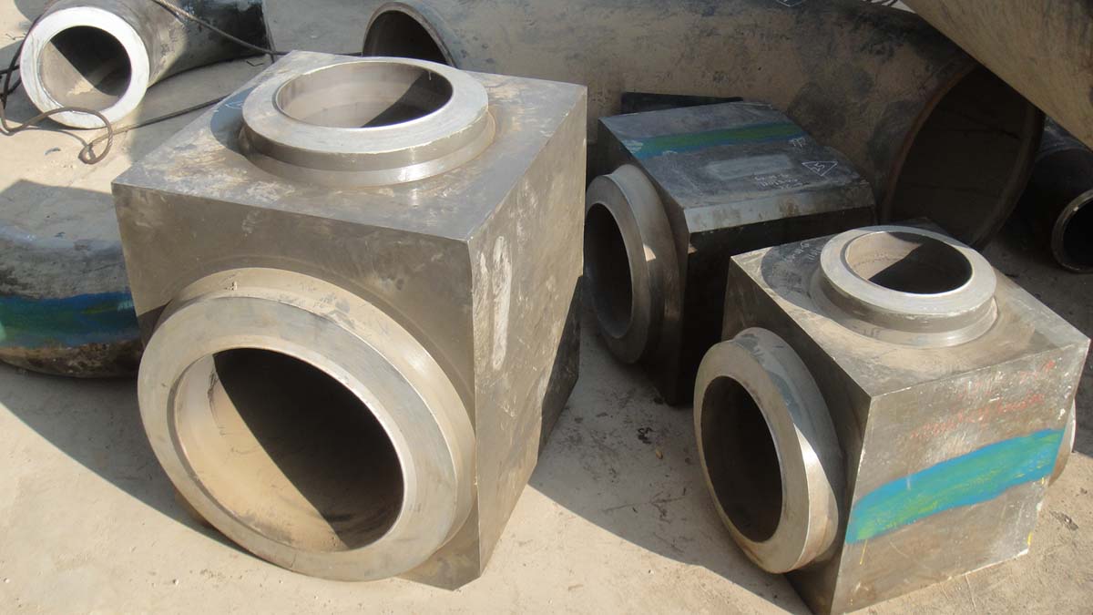
Would you mind to share a picture of the monster?

3.2
Parent - - By dragon (**) Date 12-14-2009 15:26 Edited 01-03-2010 09:22
picture is here
Parent - - By jwright650 (*****) Date 12-14-2009 15:38
My browser will not display the pictures in your link.
Parent - - By dragon (**) Date 12-15-2009 03:05
please give me you mail address, I can send you the picture.
Parent - - By jwright650 (*****) Date 12-15-2009 12:15
You can post the pictures in here. Use the attach button under your post, this will open a window and you can browse your computer, and select the picture, then check the embed image box, hit upload. Go back to your post and the picture should show up in the body opf your post.
Parent - - By dragon (**) Date 12-16-2009 10:29
Thank you! I don't know how attach picture here before your post.
Parent - - By 3.2 Inspector (***) Date 12-16-2009 11:02
Are you sure it is 12 cm thick?
I know it is very difficult to judge from this picture, but I would say it's not 12 cm.

Can you post a picture of a plain pipe end?

3.2
Parent - By 3.2 Inspector (***) Date 12-21-2009 08:08
Another one bites the dust :)

3.2
Parent - - By jwright650 (*****) Date 12-16-2009 12:07
You are welcome. :-)
Parent - - By dragon (**) Date 12-21-2009 09:43 Edited 12-21-2009 10:31
Who have good idea for preheat and PWHT this type SA335P91 material joints as per the picture. Pipe thickness is 88mm, 64mm.
Parent - By 3.2 Inspector (***) Date 12-21-2009 11:26
Who have good idea about qualifying a wps for this type SA335P91 material joints as per the picture. Pipe thickness is 88mm, 64mm.
(I dont even bother to think about the very heavy walled T pieces might require extra consideration)

3.2
Parent - - By js55 (*****) Date 12-21-2009 15:22
It seems to me you have more problems than just preheat and PWHT. As I see it your block forging is in violation of Figure 127.4.2 in B31.1. Assuming you're working to that code.
You're just askin for thermal fatigue cracks at the extreme transition you presently have.
Don't know what the European standard states as an acceptable envelope but I'm guessin it ain't far from B31.1.
Parent - - By rodofgod (**) Date 12-24-2009 23:10
Hi All!

js55, indeed these seem to be very short stubs off the forged body and are defo in violation of fig 127.4.2! However, I doubt they fall under B31.3! My guess is they are part of the main steam headers which would come under ASME BPVC?
Parent - - By dragon (**) Date 12-28-2009 04:20 Edited 12-28-2009 04:22
Hi rodofgog,
You are right, this is a Y-type reducer Tee in Main Steam Pipe of thermal power plant.
Now what  I care about is how to preheating  and PWHT this type joints with induction heating machine(Miller Proheat 35).
Any suggestion is appreciated.
Happy new year to every body.
Parent - - By js55 (*****) Date 12-28-2009 14:22
I would suggest preheating with oxy fuel. Then once the weld is complete wrapping induction coils for PWHT shouldn't prove a problem.
Parent - - By dragon (**) Date 12-28-2009 14:48
For P91 material, we should keep the interpass temperature in 220-300°c. I think oxy fuel is not a good practice.
Parent - By js55 (*****) Date 12-28-2009 16:32
Oxy fuel has been used for years on Grade 91 (natural gas as well). The problem is not the method itself but the policing of it. However, what I believe is the problem of the original post is if induction is going to be insisted upon how are you going to wrap the coils?
The evolution of specifications requiring alternative technologies for preheating Grade 91 came about because of irresposnibility on the part of fabricators and traceability of process not because the gas processes were insufficient.
In fact, in some ways gas processes are superior. For example in rolling welds for SAW.
Parent - By Jim Hughes (***) Date 12-29-2009 14:10
The following is what we do:
  Interruption in welding is discouraged.  Welds should be scheduled and staffed such that they can be completed by the end of a working shift (including overtime).  If interruption is unavoidable, then at least 3/8 inch of weld metal shall be deposited and the preheat shall be maintained until welding is resumed.

  If preheat cannot be maintained then the weld shall be given a hydrogen bake-out heat treatment at 600º F for 30 minimum (15 minutes minimum for socket welds), followed by slow cooling under insulation blankets. 

  If no welding is done for over 24 hours, welds shall be MT or PT inspected prior to resumption of welding.

  A hydrogen bake-out heat treatment shall be required for all base metals with thickness > 1.25” immediately following completion of the weld.  The bake out shall be performed by heating the weldment from the preheat temperature to 600°F and holding for 15 minutes minimum.

  After welding is complete, or after post bake as required, cool slowly to 200F or below (ambient temperature is acceptable) to allow for x-ray examination or TOFD or Phased Array and to complete the phase transformation into martensite. NDE at elevated temperature is performed by using special film protection cassettes and/or by wrapping the weld with insulation and expediting film exposure. High temp. couplants shall be use for TOFD or Phased Array.

  It is preferable that PWHT begin immediately after the NDE is accepted (Include the gamma plug weld “if used” in the PWHT).

We do info shots when our QC staff has a concern or a welder is having trouble using TOFD or Phased Array and then perform a hydrogen bake out.

Jim
Parent - - By js55 (*****) Date 12-28-2009 16:26
It won't be boiler proper. If there is a valve at the boiler outlet and the forging is in between the valve and the turbine its B31.1. No valve, and the forging is in between the boiler and the valve its BEP. In any case, the Figure will apply since even with BEP the technical jurisdiction is B31.1, the administrative is Section I.
I have had this battle many times. The forging manufacturer should know better.
Parent - By js55 (*****) Date 12-28-2009 21:45
Let me also suggest that you find out if the design engineer understood what kind of fitting he is dealing with here for calculation purposes. This thing is a failure waiting to happen.
Probably right at the transition from the pipe section to the block section. That massive hunk of steel is one big conglomeration of stress risers. This type of fitting has long history of such failures. Or, at least 'incidences' in the parlance.
Common practice is to machine these things down. Eliminating the sharp corners and radical transitions.
Parent - - By ndeguy (*) Date 12-26-2009 04:30 Edited 12-26-2009 06:01
Dragon, have you considered it will be a lot easier and just as effective to use a videoprobe to check the condition of the root bead for IP. The procedure qualification of the WPS should have proven that root-cracking is very unlikely. The bevel configuration suggests a fluxless automated welding process (unless using flux-cored) so you wont be looking for slag inclusions with the RT, perhaps stacked stop/start defects, but this should be avoidable by ensuring starts are staggered. So essentially the RT will be to check for IP.

To produce good radiographs of the root you'll need to be able to place the film internally with an external source and make the required number of exposures. If not and you intend going the much quicker panoramic route, then after arranging either sufficent cooling or to place some heat-resistant cassette backing, cut film will have to be placed in the unfilled groove in contact with the weld metal to check the root for IP. There is not much probability of detection of planar LOSWF with either technique.

As was pointed out for the fittings, there is insufficient land on the fitting side for ultrasonic Time-of-Flight Diffraction - with a 45 degree probe set up focused at 2/3rds depth on 88 mm material thickness, the Probe-Centre Separation will be 116mm, i.e  58mm from weld centre line to sound exit point from the probe wedge. Add on another 50mm minimum for the probe jig, then over 100mm of land is needed. In addition you will need  creep wave or shallow angle probes on both sides to check the 10mm near-surface lateral wave dead zone.

I hope that very through weld process control is in place.

Good luck.
Parent - - By rodofgod (**) Date 01-02-2010 23:35
Hi All!

js55, I have come across these type of boiler 'T' sections several times, in both P22 and P91 materials! I could never agree a specification! But they do exist in several power station applications in Europe at least!

I must admit that the stubs on the photos provided are short, I would expect to see more!

These welds are typically ground flush and UT is performed across the entire weld cross section!

Regards
Parent - By js55 (*****) Date 01-04-2010 14:15
"But they do exist in several power station applications in Europe at least!"

Inside the boiler?
These fittings were not uncommon a couple decades ago but some EPC's will refuse to allow them these days. And most will require severe machining of the corners and a full set of design calculations for the manufacturer before approval.
So even if the requirements of B31.1 are not applicable, there is an additional concern.

My advice would be make sure the customer approves them in writing, even if its customer supply material.
Up Topic Welding Industry / Technical Discussions / heavy thick P91 pipe joints

Powered by mwForum 2.29.2 © 1999-2013 Markus Wichitill