QC Robert
I do not agree with you or John. I cannot remember any quotable reference from an ASTM Specification, that limits the pie gauge use to "field direction" only. The ASNT training manuals are not official doctrinal manuals.
I have often used PIE gauges to verify that I can get a flux leakage indication, including the direction of magnetization, when using a Yoke, on any thick part, and when the plane of the part is in the vertical position. I have written the use of the PIE gauge into my technique sheet.
The only ASTM standard for determining field strength when using a Yoke is the weight lift verification. This is at best an offset method of field strength verification.
Whenever it doesn't seem that I am getting enough magnetic flux strength in a part, I bring out my PIE gauge for verification. I once had visually evident linear crack indications on a bridge beam web, but had been unable to develop it using a Yoke. I then verified that the lifting strength of the Yoke was adequate, and tried to develop the pie wedges with the pie gauge held "steel side" right next to the visually evident crack. Still no luck! To me this was perhaps a non standard use of the pie gauge, but it also quite clearly indicated that the field strength induced by the Yoke may have been diverted magnetically, or was simply inadequate. So now, if I cannot develop the PIE wedges on the copper side of the PIE gauge when the steel side is against the base metal , I decline to validate the test piece as "free of surface flaws".
When I have to perform MT on long girder welds, such as flange to web welds, and stiffener to web welds, I always use the PIE gauge to determine the maximum sideways width of my flux footprint, so that I can determine how far apart I can space my sideways steps and still have overlap coverage. The width of your flux field varies with the yoke leg spacing, and sometimes with the residual magnetic field in the part.
That overpriced Berthoud Gauge can also be used in a similar manner.
Joe Kane
I see your point Joe and believe that the pie gauge actually indicates both.
I believe that is why the publications author stated, "more truly" in his statement.
AS QCMike pointed out in Sec V T-7641.1, the pie gauge is used as a magnetic particle field indicator. But also in T-746.2, the pie gauge is also used for magnetic field direction.
QCRobert
QC thanks for pointing that out ill check it in the morning.
Id like to rewrite our procedure to adress direction but i wanted to check what the code said about it first.
What do think about ASME and its use of the Pie gauge.
I use it in the same way, it will tell you if a field exists and what the direction is.
Some of the weldments i check have Odd configurations so i use it to verify the direction of the field in relation to the defects im looking for.
ive never seen reference to strength and not direction ....Like ASME does.
unless ive missed it.
thanks for all the input, im going for my lvl III in MT in 2 weeks.
When i had seen ASME mention Strength and not direction i Questioned it.
this was all very helpfull.
BTW has the one leg yoke method made any headway i read an article 2 years back about it.
MDK
The one legged yoke method!!!
You want to speak to Chuck Hellier about that, and the Alaska Supreme Court. There was some testing service in Anchorage that was using that technique on the Aleyska Pipeline many years ago. They also used the "AC Drag of the Yoke" technique.
Joe Kane
It was an article i read, but never seen it use or considered.

One leg method?...Hmmm?....curious, just how do you perform the dead weight lift test with only one leg?....and what do you put on your paperwork for the leg spacing? (See ASTM E709 Table 3)
Thanks for the link...interesting.
Why Would Chuck know about it,is there a story, ill see him next month he always manages to come in for some small talk and say hi to the Students . I’m trying to build up the courage to mention that his book has a major flaw in it I wonder if he knows.
Im taking my LVL III in MT
Chuck Knows. He was involved in a big lawsuit in Alaska, and the Courts there, without any technical background, found against him. At that time the "One Legged Yoke Technique" as not endorsed by any credible organization.
I have found that the one legged yoke technique does in fact produce flux in a part.
The drag of the yoke technique was also involved in the lawsuit.
He actually gave a talk about it at the New London ASNT Meeting.
Joe Kane
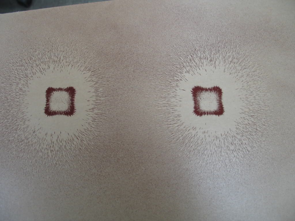
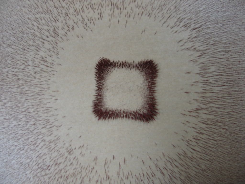
The pie gage is intended to show the direction of the magnetic flux and to ensure there is sufficient field to produce an indication. However, it does not ensure the test piece has a magnetic field that has sufficient strength to produce an indication.
You can hold the pie gage between the legs of a yoke suspended in the air and produce an indication on the copper side of the pie gage. The demonstration simply shows the indications produced on the copper side of the pie gage have nothing to do with the field strength produced in the test piece. The pie gage will produce an indication when held between the legs of the yoke with the legs pressed up against stainless steel, carbon steel, copper, or air.
Failure to understand the limitations of what the pie gage is capable of doing can result in some very unexpected results. I visited one shop where they were testing aluminum struts and verifying the field strength with the pie gage pressed against the surface of the part being tested. Amazingly, they never found any cracks in the aluminum parts tested.
The field strength produced in the test piece is influenced by several factors which include the contact area between the legs of the yoke and the test piece, the spacing between the legs of the yoke, the orientation of the discontinuity, and the permeability of the test piece. The permeability of soft, annealed iron is very high while that of hardened high carbon steel is relatively low in comparison. The strength of the magnetic field in annealed iron induced by the magnetic yoke is rather strong and capable of producing strong indications when small discontinuities are oriented 45 degrees to the direction of the magnetic flux. Indications of the same size and orientation may produce weak indications when the material being tested is hardened steel with low permeability. In both cases, a well formed indication will be produced on the copper side of the pie gage where the segments are aligned perpendicular to the lines of magnetic flux.
The single leg method will produce an indication because there will be lines of flux emanating from the yoke leg in all directions (360 degrees) around the perimeter of the leg. John's magnetograph shows the lines of magnetic flux produced by the legs of the yoke. The distance traveled through the part is very limited because the lines of magnetic flux are forced into the air to return to the opposite pole. Any linear discontinuity located close to the leg and is situated such that it cuts across the lines of flux in the part will produce an indication.
A gage that uses the "Hall Effect" is capable of measuring field strength with some degree of accuracy. Some people check the operation of the magnetic yoke by lifting the weight bar and then checking the pull produced in the test piece if there is a question about the adequacy of the magnetic field produced in the part. If the yoke is strongly attached to the test piece, it can be assumed that the strength of the magnetic field is sufficient if the same leg spacing is used as when the weighted bar was lifted.
NAVSEA requires the yoke be capable of producing an indication when a 1/16 inch long notch oriented perpendicular to the longitudinal axis of the bar is present. The spacing of the yoke legs will influence the ability to produce an indication. This approach is a step up from simply lifting a weighted bar. It seems reasonable that if the yoke can lift the bar with the appropriate weight and produce an indication at the specified leg spacing, the same discontinuity should result in an indication if the yoke is attached to the test piece with the same strength/force when the legs are similarly spaced.
Best regards - Al
I would agree with Al, here is one thing to remember. The yoke produces a magnetic field, even in air. Laying a pie gauge within that magnetic field only tells you that its there. It doesnt not ensure that you will find defects within the part being examined. The only way that I know of to ensure that a given yoke will find indications is to examine a similar piece with a known flaw.
d
And thats why i questioned the way ASME used strength.
.

 Forum
Forum


