Not logged inAmerican Welding Society Forum
Forum AWS Website Help Search Login
Up Topic Welding Industry / General Welding Discussion / Welded Rail Road Track
- - By yojimbo (***) Date 07-01-2011 20:43
Gentlemen-

I am preparing a bid for a project that will incorporate RR track as an architectural/structural element and would appreciate your input/ direction/advice.  The architect intends to use salvaged railroad track for a walking surface and the surface will require welding.  Here is the best written description I can provide:  2 carbon steel structural members-channel- laying parallel to each other and embedded in concrete will support perpendicularly located RR track inverted so the base of the track is the walking surface and the rounded "head" of the track is welded to the supporting structural members.  The bases of the track will be gapped 1/8" and welded to each other [no welding spec or dimension is provided] and the walking surface is to be "hardfaced" with diamond pattern weld beads for traction. The "hardfacing" is only an expression, it's function is for tread not wear resistance.  The project manual spec. refers to thermite welding which is I think being misunderstood and applied by the architect as the proccess is as we know used to fuse tracks to each other for railcar use and to my knowledge the ceramic cofferdams used to hold the thermite are constructed to that purpose not to the radius bevel joint for joining the inverted track head to the structural member.  I suspect the spec on thermite welding was used generically without full understanding.  So, some questions:  RR track steel- ASTM 1 I am told is weldable using SMAW.  True?  Regarding dissimilar metals- RR track to structural member-  SMAW compatable?  What should I be looking to for electrode?  Suggestions for developing an applicable welding procedure if required?  This is going to be an interesting job and one of the GCs I am already working with will be bidding so I would like to pursue this somewhat aggressively but will need to educate myself [and the architect, cause you're just not allowed to shoot them anymore] in order to get the pricing right and not shoot myself in the foot instead.  Anyone want to wade into this one with suggestions, I am all ears and look forward to your comments.  The project also incorporates several tons of Corten steel both structural and architectural so if those better acquainted with these issues have backrounds on both I would greatly appreciate what you have to say.  Please feel free to pose any questions for more specific material/spec information and I will provide it.  Thanks in advance.
Parent - - By Bob Garner (***) Date 07-01-2011 21:24
I concur with you on the thermite process being a process to splice rails and is likely misunderstood by the Architect.  We also spec manual rail welds but I will have to see what we did for chemical analysis/requirements.

Bob G.
Parent - By yojimbo (***) Date 07-02-2011 00:17
Bob-

Thanks that would be a great help.
Parent - - By DaveBoyer (*****) Date 07-02-2011 03:17
I did see a demonstration of thermite welding railroad rail at the Quad State blacksmithing conference. It was a but joint of the rails, as You described. Some rail may be weldable without concern for carbon equivilent, but some rail is heat treatable with 40-60 point carbon, so they will have to be sure of what they are using.

To Me it sounds like a lot of grief to go through to build a walk, but I am probably not refined enough to understand the artistic value of it.
Parent - - By yojimbo (***) Date 07-02-2011 16:17
Dave-

The rail track supplier I have sourced told me the steel is ASTM 1 and I would be able to determine the metallurgy from that spec which I have yet to do.  From limited knowledge and a more limited memory that doesn't sound like a recognized complete spec so I have some work there.  I expect something suitable can be figured out and a welding proccess can be determined to join the tracks to the structural supports.  As to the materials suitability based soley on it's "artistic" value, please reference the caveat in my original post regarding the restraints currently in place regarding limiting the longevity and sustainability of architects.  Can you expand on your reference: 40-60 point carbon?  I am not familiar with that nomenclature.  Is it used and addressed in the Lincoln Handbook of Arc Welding?  I'll have to look as that is my primary reference for questions like this.
Parent - - By DaveBoyer (*****) Date 07-03-2011 01:04 Edited 07-03-2011 01:06
40-60 point carbon means that the carbon content is 0.4%-0.6% carbon, definatly heat treatable particularly at the mid to upper end of the range.

Old railroad track is a poor man's substitute for tool steel in the blacksmithing community. You heat a piece to non-magnetic and quench, if it gets hard, You use it as tool steel. A little more experimentation and You get an idea how to temper it.

Carbon isn't the only alloy of concern, so to properly calculate the CE You need the full material analysis [not something I know how to do].

I am not familiar with ASTM specifications, only SAE an AISI.
Parent - By ssbn727 (*****) Date 07-03-2011 07:45 Edited 07-03-2011 12:23
"Element" is the word - Dave (I know what you meant buddy:lol::wink::cool:)... You're right regarding the elements, because one also needs to find out if there's a certain amount of manganese in the rail as well, and not all rail is made with the same percentages of the necessary elements to make up their alloy grades of steel...

The first steel rails used anywhere in the world were laid in Derby station on the Midland Railway in 1857. The metallurgical structure of those rails was essentially the same as that of the rail steel still used today - a pearlitic structure based on a carbon/manganese composition.

All that the rail maker has done in the last 140 years is to refine some of the basic features around the fundamental structure:

Pearlite comprises a mixture of relatively soft ferrite and a hard, brittle iron carbide called cementite, taking the form of roughly parallel plates. It achieves a good resistance to wear because of the hard carbide and some degree of toughness as a result of the ferrite's ability to flow in an elastic/plastic manner.

Microstructure of PEARLITIC rail steel. The interlamellar spacing is about 0.3 micrometres. This is a colour enhanced image in which the cementite is light blue and the ferrite is black. 


Chemical control is very accurate, with carbon and manganese at optimum levels... Potential embrittling elements such as sulphur, phosphorus, nitrogen and hydrogen are controlled at low levels, and the steel is "cleaner" with fewer stress-concentrating entrapped inclusions from the steelmaking and casting process.

Alloying elements such as chromium and nickel can be added to some rail steels to improve properties. Alternatively, the rail can be cooled quickly to reduce the time available for diffusion. The rail can also be heat treated.

The first British Standard for rail steel manufacture was BS11 issued in 1903 which required a minimum tensile strength of 618 N mm-2. (It is interesting to note that four of the first eleven British Standards written were on rails or railways, indicating their importance to the country's industrial development at the turn of the century). Since then, there have been twelve revisions leading to the current 1985 edition. Strength requirements are now 710 N mm-2 for the "Normal" grade and 880 N mm-2 for the so called "Wear Resistant" grade.
High Strength Rails

The last 20 years have seen further increases in strength, mainly to cater for the heavy axle loads of North America and "Premium" rails of around 1300/1400 N mm-2 tensile strength, (1 N = 0.102 kg force) are now used in large quantities. They are finding increasing use in European railways in tight curve/high wear situations. THese high strengths are achieved by making the spacing between the pearlite lamellae finer by controlling the growth rate of pearlite.

Alloying elements such as chromium and nickel can be added to some rail steels to improve properties. Alternatively, the rail can be cooled quickly to reduce the time available for diffusion. The rail can also be heat treated. British Steels' rolling mill at Workington was the first European railmaker to introduce a heat treatment process in 1985.

Combinations of alloying and heat treatment are possible and a range of grades can therefore be produced. Figure 1 shows these in terms of hardness properties and the corresponding resistance to wear. A railway's choice of rail grade is made in terms of traffic and track conditions and excellent service life can be achieved, particularly if modern rail head lubrication and grinding practices are used.
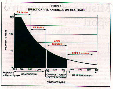


Figure 1: Plot of the wear rate (mg m-1) versus hardness (HV) of rail steel. Hardness is the ability of the material to resist penetration by a specified indentor.

The Need for New Rail Steels

Rails not only wear, they also break. Their inherent toughness is poor as a result of the presence of the brittle carbide phase. Fracture can occur from relatively minor stress-concentrating features inside the rail, or on the surface, as a result of manufacture or subsequent handling damage. At least one European railway network suffers almost 4000 rail fractures every year. These are rarely dangerous, as modern track signalling systems and routine inspections will find most. They do however have a high replacement cost and can be very disruptive to the network.

Pearlitic rails have been developed almost to their limit and British Steel as a major supplier to the world market therefore asked itself, "What other structures are available? Do any offer better properties?" The answer is "yes".

"Steel" is an extremely versatile material. If a suitable series of small alloying additions are made, or the correct heat treatment chosen, then other types of structures can be produced.

Low Carbon Carbide-Free Bainitic Steel

Correct choice of alloys and an intermediate cooling rate can produce a bainitic structure. This structure, like pearlite, normally contains ferrite and carbide, but in this case the ferrite is semi-coherent with the high temperature austenite phase from which it was formed.

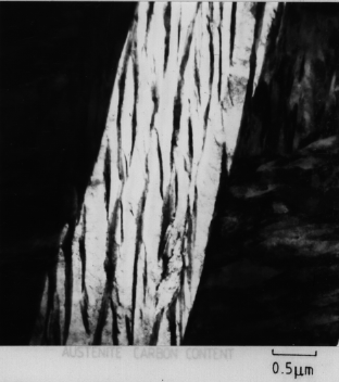
Microstructure of BAINITIC rail steel. The width of red layers is about 0.8 micrometres. This is an optical micrograph which does not reveal the true fine structure of the bainite which contains plates that have dimensions less than 0.2 micrometres (a higher resolution transmission electron micrograph is available showing these fine plates with intervening austenite films Figure.).
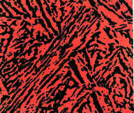


Alloying additions are made to prevent the formation of carbides, resulting in very fine interlath films of austenite which are retained between the ferrite plates. The structure is composed largely of low carbon carbide free bainite with some retained austenite. Figure below.

This novel low carbon bainitic alloy was developed in collaboration with Cambridge University and has been patented world-wide.

The new steel has the advantage of forming the desired structure under normal conditions after rolling the rail.


Properties of the New Steel

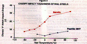
The first casts made were aimed at a similar strength to conventional heat treated rails. The new grade shows a dramatic step change in toughness. The new grade shows a dramatic change in toughness. Figure 2 illustrates the improvement, across the whole range of temperatures encountered by the world's railways. At low temperatures, where rails are most vulnerable to fracture, for example, properties are improved by a factor of 5 to 1 at 0 °C.

Plot of the impact toughness of bainitic and pearlitic rails. A larger Charpy value indicates a greater ability to withstand impact deformation and a lower sensitivity to concentrations of stress.


More modern fracture toughness tests, which tend to group all pearlitic rails in the same low range, show significant improvement. This improvement in toughness significantly increases the size of crack which can be tolerated in service without causing fracture - by up to 2.7 times, making it easier to find defects and replace rails in a controlled manner.

Table showing the fracture toughness of pearlitic and bainitic rail steels. The larger the toughness the greater the size of cracks that can be tolerated without failure.

Pearlitic: 30-35 MPa - m0.5

Bainitic: 50-60 MPa - m0.5

For similar hardness levels the bainitic grade shows a reduction of 4 to 1 in rate of wear in the laboratory and only slightly less under more complex track conditions. Also the laboratory tests indicate potential benefits for reduced wheel wear for the new bainitic grade. Full wheel size wear tests are currently being undertaken.

The formation of very fine surface cracks by a phenomenon of rolling contact fatigue is of increasing concern to European railways. In separate trials in the UK and at a recognised European railway test centre for full scale testing, the new bainitic steel showed dramatic improvements in comparison to the traditional pearlitic rail. The whole wheel/rail test showed crack initiation at two hundred and twenty thousand cycles on traditional pearlitic premium rail, whereas after one million cycles the new rail steel was crack free when the test was terminated to permit further trials to take place.

The new steel is in service in British Steel S****horpe's Works industrial track with conventional (25 tonne) and heavy (50 tonne) axle loads and is performing as the laboratory tests would indicate.

The new steel therefore shows considerable potential in terms of life in track, reduced maintenance, increased safety, with anticipated reduction in rail fractures. Testing which began in 1995 in industrial track will be extended to the USA's Facility for Accelerated Service Testing (FAST) track in Pueblo, Colorado later this year. Following anticipated successful results at FAST, trials will take place with selected railways in the Spring of 1997.
Mr J. K. Yates
Manager, Product Development and Technical Support
British Steel Track Products

Here's some more info:

http://www.msm.cam.ac.uk/phase-trans/2002/rail.pdf

Wear

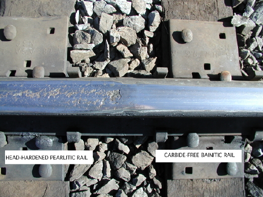
The following image has been provided by Kevin Sawley, who ran trials of an experimental bainitic rail steel on heavy-haul track in the USA. The steel was had the chemical composition Fe-0.26C-2Mn-1.8Si-1.9Cr-Mo-B. It had an as-rolled hardness of about 415 Brinell and toughness of about 50 MPa m1/2. The spectacular picture that shows conventional head-hardened pearlitic rail flash-welded to the carbide-free bainitic rail following a trial in which 90 million gross tons of traffic traversed in a sharp curve. The superiority of the carbide-free bainitic rail is fairly clear.

The work was done at Transportation Technology Center, Inc.


Here's some other interesting information regarding rails of pearlitic & Bainitic structures courtesy of Cambridge University & their illustrious Department of Material science and Metallurgy:

http://www.msm.cam.ac.uk/phase-trans/2011/JG/1.pdf

http://www.msm.cam.ac.uk/phase-trans/2011/JG/2.pdf

http://www.msm.cam.ac.uk/phase-trans/2011/JG/4.pdf

http://www.msm.cam.ac.uk/phase-trans/2011/JG/5.pdf

http://www.msm.cam.ac.uk/phase-trans/2011/JG/6.pdf

http://www.msm.cam.ac.uk/phase-trans/2011/JG/7.pdf

http://www.msm.cam.ac.uk/phase-trans/2011/JG/8.pdf

Well, that's about it for now... I think this should be enough "to chew on for awhile.":confused::roll::eek::lol::wink::cool:

Respectfully,
Henry
Parent - - By 99205 (***) Date 07-02-2011 16:53 Edited 07-02-2011 17:04
A while back I read an article about SMAW (7018) on R/R steel.  If I remember correctly there was an issue with preheat and welds breaking off if the weld was on the working side (top or ball) of the rail.  If I can find the article I'll put it up.  Not the article I was looking for but kind of relevant.

http://www.tinmantech.com/html/faq__welding_railroad_rails.php
Parent - - By yojimbo (***) Date 07-02-2011 21:56
99205-

Thanks for the heads up, just the kind of information most architects wouldn't have.  I anticipate pre and post heating but again the "designer" has probably not considered it or the cost and time.  The related article is helpfull although I am not familiar with that electrode and have only run 7/32 7024 on my Classic III it might push a 1/4" electrode without having to rent a larger power source, which is not that big a deal anyway.  If you run across the other article please forward or post a link, sounds like very usefull info.  The pre-bid meeting is this coming Thurs. 7/7, and I'd like to be up to speed on these issues. Will likely try to locate an experienced RR welder this week and see what I can learn there as well.  There are some repair facilities locally for the RR I might be able to access. Thanks.
Parent - - By slagline 3 (**) Date 07-04-2011 22:53
You are not building something to rail road standards anymore, you are going to be fabricating something completely different. The rails now are just going to be an architechural element. The rules change. These members now will be in compression....
Parent - - By DaveBoyer (*****) Date 07-05-2011 00:36
The rail cap will now be in tension between the supports, and it may have cracks from it's former use. No mention made of the length of the rail sections, or the distance between supporting channels, but there is probably enough material in the rail's bottom flange to carry the load with little deflection, unless this is a really wide walk.
Parent - - By yojimbo (***) Date 07-05-2011 17:57
Gentlemen,

I'd like to express my appreciation to all of you for your insights, information and interest.  Henry, your reply was encyclopediac. The chewing will be a big enough challenge, the digestion of another order.  I am intending to commit it to memory before this weeks pre-bid meeting so I can corner the architect and so overwhelm him with the technical deficiency of his understanding of steel design that his jaw goes slack, his eyes glaze over and he starts backpedaling untill he changes his bridges foot path to RR ties instead of RR track.

On a serious note, I stopped in to the RR locomotive repair shop down my way this morning and spoke with an engineer who more or less shrugged off the whole problem of welding advising I treat it like any other and nothing special.  He broke out his AISC steel design manual and we looked at the track rail section diagrams, and saw where the steel spec. was ASTM A759, so that's a start on material spec. but needs to be confirmed and I am of the opinion the engineer's lack of concern regarding welding procedure is a mistake.   It will be solvable but there are other concerns:

For any of you with a continuing interest I would like to bring into discussion another project relevant and industry relevant phenomena-  Designers who don't "design".  You all probably know where this is heading, have likely run into it yourselves many times and share the same frustration.  Drawing Cad schematics of unconstructable or technically ill informed construction plans is not "design".  It is drawing pretty pictures that look good on paper.  Somewhere lost in an old hard drive is a brilliant article I downloaded some years ago when I hung my shingle and first encountered this practice of "designers" that relieved themselves of most if not all responsibility for their paper creations.  The article written by an engineer took them to task to remind them of their responsibilities to provide the workable details and scolded them professionally for placing that burden on fabricators.  It is not that fabricators are incapable of apply "best construction methods" in order to achieve the intents of the architects, but it is not our jobs, or when it becomes our job we need to get paid for it.  If the project spec. manual dictates shop drawings stamped by a PE, so be it, I can specify stamped drawings in my bid proposal and charge accordingly.  This project takes complacency and avoidance to another level.  The Division 5 spec does not dictate stamped shop drawings, it does however include language to the effect that the architect takes no responsibility for the design considerations necessary for fabrication.  I will dig up the exact nomenclature in the next day or so for your evaluation.  It becomes an even more interesting discussion when we are talking about public works projects- such as this - in that the firm that produces construction plans are already paid for their documents by the time it goes to bid.  Pre-bid RFIs are often skirted in response and the GCs of course don't even usually want to know about the details.  "Bid the documents" is the most often heard response, which leaves so many gaping holes and "plausable deniability" that accurate and responsable pricing becomes difficult at best.  Having to note exceptions and propose workable alternatives in a bid muddies the water and what too often happens is the GC simply looks at the price a fabricator submits who has not accounted for drawing conflicts and can offer a lower price that gets them the job they will then need to jack someone up in order to build it as it needed to be quoted.  Show them the pitfalls in the bid, and the price it is actually going to cost and you're too high.  My apologies.  I meant to simply introduce a subject of additional discussion.  I did not intend for it to become a ranting of my pet peave.  Maybe there are those familiar with this disingenuous process of public expenditures and have insight toward strategies of self protection and competitve bid winning pricing?
Parent - By DaveBoyer (*****) Date 07-06-2011 01:50
If You bid high enough to do the job responsibly with proper engineering and fabrication practices, You probably won't get the job.

Whoever does get the job will do it substandard or loose his but, perhaps both.

I would bid it high enough to make profit doing everything needed, great if You get it, so what if You don't.
Parent - - By raftergwelding (*****) Date 07-06-2011 05:30
I was hired to do a rail road job once and we welded the track down with 1/8 & 5/32 7018 and didnt have any troubles with the welds. And yes it was carrying the train with its cargo being vehicles carried into a yard where they unload the cars.
Parent - - By yojimbo (***) Date 07-06-2011 14:44
Rafterwelding-

Do you remember whether you were required to take a weld test for that job and if so what the test procedure was?
Parent - - By raftergwelding (*****) Date 07-07-2011 05:29
No test i got the called showed up the next day rolled out and burned rod all day long was suppose to take a week we (2 of us) knocked it out in a day mostly me his yanmar converted short hood played out and i took up the slack
Parent - - By Sberry (***) Date 07-11-2011 02:24
If its truly artistic it should be designed in a way that the welding basically holds it in place for shifting, maybe not really structural? Right or wrong over the years have welded several things to RR track with lo-hi, even beat on some of it pretty good with heavy equipment, never had it tear up even with some pretty substantial shock, not very scientific but doubt this structure would be subject to being rammed with a D7 or loader.
Parent - - By raftergwelding (*****) Date 07-11-2011 05:20
When i can find it i use it to build cattle gaurds out of
Parent - - By yojimbo (***) Date 07-11-2011 15:25
RCwelding-
Thanks for the info on your experence.  I am assuming you guys were just handed the electrodes to use when you got to the job meaning the RR owner made the weld procedure decision.  I amy need to qualify a procedure or at the minimum provide supporting documentation that 7018 will do the job and meet structural requirements.  But your experience point me in the right direction.  I put in an RFI to the owner regarding their thermite welding spec. and expect a response tommorrow which should tell me what I need to do next.  Project bids 7/20/2011 so plenty of time left to herd the ducks up in a row.   
Sberry- the rail track is going to be a walking surface supported by structural members and there is a 3/8" weld dimension on the contract drawings so my guess is an engineer has given it a look at some point to address the structural requirements of attachment. 
I should be getting the replies from the owner to questions this week and will need to line up a CWI for weld quals. and paperwork which I'll do in a different thread.  Want to thank all of you that have contributed your thoughts and insight to date.
Also RC- there are a number of distributors that specialize in salvage RR track.  I don't know where you are acquiring the track you use but the supplier I've located is getting about .30 # for used track, grade 3 [the low grade] and rail is measured in pounds per yard, usually 90# per yard.  The distributor is in Portland OR. so shipping could be a cost factor for you being in TX as I recall.  Gotta be a local to you supplier I would think, takes a lotta Santa Fe rail track to get across TX.
Parent - - By DaveBoyer (*****) Date 07-13-2011 04:04
Just be sure they can supply the entire lot with the same "depth"- top of the head to bottom of the base.

One of the guys at the flea market asked Me how much 1 rail from Redding, Pa. to Philly Pa. would weigh, so I looked up rail specs on the net so I could give a rough guess. Turns out there are a whole lot of sizes from every rail co. & the A.S.C.E.
Parent - - By yojimbo (***) Date 07-13-2011 14:38
Dave Boyer-

Very good point.  Thanks for the heads up, I need to keep that in mind considering it's application.  I spoke at some length with the RR track suppler yesterday.  The spec had called out a track rail of a specific manufacturer my supplier informed me was no longer made and would only be located somewhere on the east coast.  He had an alternative rail track and the difference in dimension was in the base, about a 3/8" difference so no big deal.  But he also mentioned "head wear", where the track head gets worn down by usage.  Fortunately it less than 1/8" but could still present installation headaches.  Never occured to me to consider it and had been assuming it would all be produced to a specific size, which it is but like any material it's neccessary to know tha allowable variation in dimension. Fortunately he has sufficient stock in hand from the same maufacture or at least the same spec to furnish the lot.  Food for thought, thanks, will speak to the supplier about this.
Parent - - By yojimbo (***) Date 07-26-2011 19:57
This project which many of you have helped me with is yet to be awarded to the GC but I am in discussion with the lowest apparant bidder and the owner and looking to get ahead of the curve should we get the contract for the fab and install on the job.  A concern I am trying to resolve regards applicable welding procedures for the referenced RR track weld.  Contract documents specify using Prequalified AWS weld procedures.  There are two issues with this spec. for me. 1] My only reference is the Lincoln Handbook of Arc Welding.  I have gone through the section on SMAW welding procedures [we will be welding this with stick] and I do not see a Flared Groove Weld configuration that would conform to the geometry of a RR track head being welded to a flat surface such as a wide flange beam, which is our application.  2] I do not understand the requirement for qualifying a procedure for this application regarding matching materials. ie. would a procedure actually need to be qualified using RR track and a structural member of A588 steel, again that is the actual application. Can a procedure be qualified using plain A36 and a similar joint configuration and if so, is there a prequalified procedure that would meet this joint configuration?  All welding will be done in the flat position.

Is there a prequalified AWS procedure that will meet this application?

I've outlined a scenario to the owner's representative, a practical guy I've worked with before who's goal is just to get the job done, suggesting we simply weld a piece of track to a piece of A588, have it MT inspected and then beat the daylights out of it with the biggest sledge hammer we can swing.  He understands the practicality of this "testing methodology" but I am looking for something a little more industry and engineer acceptable.  Your suggestions on the course of action needed is much appreciated.
Parent - By jwright650 (*****) Date 07-26-2011 20:31 Edited 07-26-2011 20:40
What size rail section is this that you are working with? We built some material handling buggies here in the shop that use a 40# rail that was welded down to plates(metal cross ties) then bolted to the concrete floor. These rails see fairly heavy loads daily and lots of shock loads at the rail's dead ends due to the stops. We used 3/32" E70T-1 with 100% CO2 and these rails have been in service since 2005 and they haven't had any problems as of yet with any of the welding.

EDIT*
Another thought, rather than guessing what material is in that used rail, maybe suggest that they purchase a new section of rail and then they could use a size that can be used to calculate the required loads and whatnot. http://www.akrailroad.com/how-to-order
Parent - - By fschweighardt (***) Date 07-27-2011 11:54
Better get the rail base metal specifications worked out, if you want to use prequalified procedures.  Did they say what code and what edition you need to work to?
Parent - - By Jacob Reverb Date 07-27-2011 12:16
Wow, thank God for architects.
Parent - By yojimbo (***) Date 07-27-2011 23:53
Jacob- that posting is inappropriate, offensive and made me spew coffee all over the keyoard.  Humor has such an inherent malignancy to it.  Must be why laughing feels so good, it disperses the suffering we would sympathize with otherwise.  There's instant karma for you though- my laughing is gonna cost me $100 to get the laptop dried out and fixed.  fschweighardt- I tried to get that info from the track supplier at first, need to check my notes but his ASTM spec. did not cross reference a steel metallurgy.  I will go after it again and it will likely provide a lot of the answers. JWright- as I am beggining to suspect the track will do plenty fine with some good basic 70XXX electrode.  This is only a pedestrian walking surface.  Aint gonna be no choo-choo trains rollin on it no matter what the architect wants to see.  Talked with some very knowledgeale guys today from the Ironworkers Local, they steered me to a guy I know in the supply bisiness who is also a CWI and is glad to write procedures when it's gonna produce supply sales.  Was indicated that NDT would probably suffice for procedure qualification with the owner, so etch it or mag it and cut the flared bevel test weld open for visual.  Welders test qualification with the same welding process will probably hold more weight with the owners than procedure quals. is what I am hearing.  It is after all not bridge work and the owners rep understands this as does the GC.  Spent some time on this project so far and won't know if I'll get it for another 10 days, so I'll try to cross a few more Tee's and dot a couple more Eyes and wait for someone to cut bait.

Uh oh.  5 O'clock.  Judge Wapner.  I'm a very good driver.
Up Topic Welding Industry / General Welding Discussion / Welded Rail Road Track

Powered by mwForum 2.29.2 © 1999-2013 Markus Wichitill