Not logged inAmerican Welding Society Forum
Forum AWS Website Help Search Login
Up Topic American Welding Society Services / Technical Standards & Publications / Another Damn Weld Dam?
- - By Skaggydog (**) Date 09-17-2011 19:16
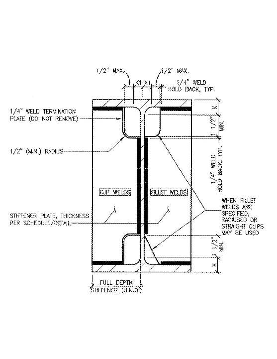
The design prints say work to D1.8 and also state "no weld dams".  On the same page is this sketch of the continuity plates and stiffners.  Top left, what the damn is that?
Parent - - By 99205 (***) Date 09-17-2011 20:48 Edited 09-18-2011 05:39
If you notice on the right side of the beam, there is a hold back for the weld termination point.  This is most likely to prevent the development of a stress riser, if the weld were to terminate at the corner.  For what ever reason, the engineer needs the welds to travel the full length of the stiffener on the left side.  To prevent the development of a stress riser on the left side, the engineer has designed a plate for the weld to tie into.  My question would be, how wide is that termination plate suppose to be.
Parent - By 803056 (*****) Date 09-17-2011 21:04 Edited 09-17-2011 21:14
Dams, in the sense used by D1.X welding codes, are blocks of metal placed at the ends of the groove to prevent the liquid weld pool from spilling out of the groove. Slag inclusions can be found at the ends of the weld beads in the completed groove weld when dams are used.

Extension tabs or run-off tabs are the preferred method of extending the groove to ensure sound weld at the ends of the groove weld.

Best regards - Al
Up Topic American Welding Society Services / Technical Standards & Publications / Another Damn Weld Dam?

Powered by mwForum 2.29.2 © 1999-2013 Markus Wichitill