I'm trying to detail a drawing for a fabricated hinge, but I'm unsure of what (if anything) to place for the "arrow side" of the weld symbol. The "other side" of the symbol (I believe) would be a standard Flare-bevel-groove weld (BTC-P10-GF). This joint looks similar to a PJP T, Y, and K Tubular Connection as shown on page 118 (of the D1.1 2010 edition), "side matched".
Would it be per D1.1 code if I place the flare-bevel-groove weld symbol for the "other side" and a fillet weld on the "arrow side"? Or would I have to place a flare-bevel-groove weld symbol for both sides? Please help me with this, thank you.
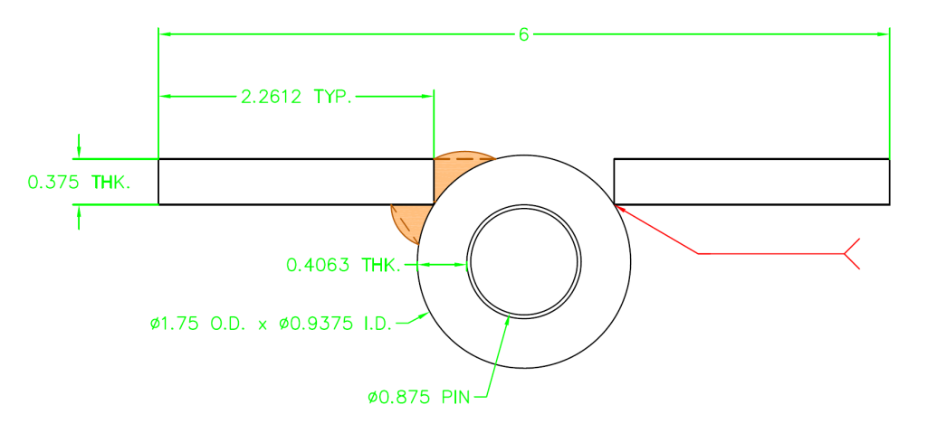
Below is a picture of the joint and materials.
I believe I would opt for flare bevels on the other side and reference a "detail" for the arrow side. The arrow side approximates a skewed T-joint. Depending on the dihedral angle at the point of tangency, I would size the welds as if it was a skewed T-joint. That is, if the angle is less than 60 degrees, consider the Z-loss. A sketch of the joint will provide a means of detailing the required dimensions of the "leg" and required throat with due consideration for the Z-loss.
My philosophy is that if there is a question whether the joint is a fillet weld, groove weld, skewed T, etc., a sketch tells the story without complications or question. Standard welding symbols serve a useful purpose, but they don't necessarily fill the bill for every conceivable configuration.
The sketch you included in the post is nearly complete, just add the dimensions. Keep in mind there is little probability of achieving CJP or fusion at the root of either side of the joint shown in your detail.
You can verify what weld size is reasonable by welding a mock-up and sectioning the weld in a couple of locations. The mock-up will serve as your qualification provided you document it as you would when qualifying a PJP.
Best regards - Al
Thanks for the reply. Using the minimum weld sizes for PJP's and showing a detail illustrating the leg sizes and effective throat with the appropriate z-loss, would the "arrow side" weld be considered pre-qualified? I just noticed that you mentioned documenting the mock-up as for when qualifying a PJP; we're wanting to try and stay in the pre-qualified range for all of these welds. If it's not possible, I understand.
I do not believe too many people would take issue if you approach the arrow side as a skewed T-joint with groove angle of less than 60 degrees, taking into consideration the Z-loss. As long as the welds are sized based on the requirements of a prequalified joint detail you should not encounter a problem.
I don't believe a standard welding symbol would be suitable for the arrow side. A sketch would be less confusing to the person attempting to deposit the required weld.
Best regards - Al
With church last night I didn't get a chance to post until this morning.
If I understand Al correctly I agree with him. I would say the welds on both sides of the hinge are in flare bevel joints. Even though one is very close to being a "fillet" weld.
Depending on your usage of this I would follow Al's suggestions on verifying the depth and calling out the dimensions on the drawing. You may not have to go that far if it is only for some industrial or residential gates. But, it doesn't hurt in any situation to be accurate and detailed. That way the responsibility lays with the fabricator/welder to make sure it is as you have called it out.
Have a Great Day, Brent
Eddie,
A couple of additional comments...
The reason, to me, why I would call both out as flare bevel is the size of the radius on the hinge. Even though with the weld's location and angle the drawing very closely resembles a fillet weld the radius would include it to be considered as a flare bevel. The 'opposite' side is even more so. Thus, both sides would be drawn as flare-bevel. Now, the application would probably work if you did as you said and called the one just a normal 'Fillet Weld'. But, IN MY OPINION, it is more proper to call both sides a flare-bevel.
Also, I would note 'TYP' in the tail to apply to the welds on the other side of the hinge. (I am assuming the two sides are at different levels so they are welded independent of each other and are not keeping the opposite facing plates on the same rotating pin? We are looking at an end view, if we saw a side view one plate would be on top and the other underneath on two different parts of the hinge?) If your arrow only points to the one weld joint it should be noted that all similar joints will get welded the same. Arrow side and opposite side weld symbols on your welding symbol reference line only indicate the two welds at that particular joint.
Have a Great Day, Brent
Al, I'll definitely use a detail instead of a standard welding symbol for a skewed T-joint, now that I know a little more about the requirements.
Brent, I see what you're saying about calling both sides a "flare-bevel", but my concern is with the tolerances the book gives for the the "f" value, which in this case would be 0.1875" minimum, and minus 0.0625" as fit-up. Since the plate isn't even meeting the tangent of the circle, then the "f" vault would be equal to a negative number. What are some thoughts on that?
I will put a further clarifying note on the drawing and show a plan view (the above being the end elevation view) that will depict the actual weld at ever other knuckle on the left and right sides of the hinge.
Whenever tolerances allowed in a code calculate into negative numbers they become '0'. Take a root opening tolerance that can be (hypothetically) 0-1/4" +or- 3/16". It could then be -3/16". We all know that isn't going to happen. So, it is an automatic '0'.
Now it could happen that this is not always the case, but a majority of the time this will be true.
These situations are not of concern, especially to the designer/detailer. You need only draw it as you want it. The Fitters deal with that and are required to stay within the code tolerances. If those numbers come into a conflict because of negative values they will just put the parts in direct contact or must modify the parts, within those tolerances, to get the overall dimensions to come out as desired.
Have a Great Day, Brent

 Topic American Welding Society Services / Technical Standards & Publications / Fabricated Hinge Weld/Joint Type

