Not logged inAmerican Welding Society Forum
Forum AWS Website Help Search Login
Up Topic Welding Industry / Inspection & Qualification / References on prints
- - By CB05829 Date 06-13-2013 13:04
Can someone give me a thoruogh definition as to what the REF actually means on a print, or let me know where I could get one. I just need something that I can post on the shop floor to eliminate any confusion between the fitters.

Thanks Chris
Parent - - By welderbrent (*****) Date 06-13-2013 13:14
You might start by telling us where it is located on the print?  Such as, in the tail of a welding symbol?  A location that may be sending the fitter to a detail?  It can mean many different things.  And heaven forbid all engineers would use it in the same way.  Or place it in the same spot. 

If it were easy anybody could do it. 

Have a Great Day,  Brent
Parent - - By CB05829 Date 06-13-2013 14:12
Just for an example on the drawing they will give the length as 96.00in (REF) Height 52.00in (REF). There are two prints the first print tells you that the part needs to be cut and has a tolerance of +/- .50".  The next print is the final assembly, this one has the
(REF) on it. I understand what they are doing just having a hard time trying to give the fitters a good explanation.

Chris
Parent - By welderbrent (*****) Date 06-13-2013 14:29
Even in large structural members I have not seen many drawings that had a +/- of .50".  I believe the object is to point out that the dimensions of 96.00 X 52.00 are estimates and not accurate.  In many of my projects what will be stated is that 'All dimensions are to be field verified by the contractor' or something to that effect.  So nothing is truly final until the project is at a point where the Fabricator can finalize measurements on key structural members.  At the point the final revision of shop drawings can be approved and construction begins on those members. 

Hope that helps.

Have a Great Day,  Brent
Parent - - By jwright650 (*****) Date 06-13-2013 14:37
Chris are you working with Structural shapes, like Wide Flange beams and columns, plate, flatbar, channel, angle....etc?

If so, many codes and specifications refer to ASTM A6 and from A6, you can find all of the rolling tolerances for a shape(height, width, thicknesses...etc). The tolerances for the amount of sweep and camber that is permissible for the length of the member is also spelled out.
Parent - - By CB05829 Date 06-13-2013 15:27
Ok! I think we have an answer. The reference refers to a dimension elsewhere on the print or on a previous print, as double dimensioning is not premitted.  All reference dimensions should be held to the tolerances stated on the original print.

Thanks for all your input.
Chris
Parent - - By Milton Gravitt (***) Date 06-14-2013 02:52
Chris were I work they want hold you to a measurement in (reference) but we try to stay within the tolerance range and you are right about double dimensioning of a part.
Parent - By Milton Gravitt (***) Date 06-14-2013 03:14
I just found this http://wiki.answers.com/Q/What_is_a_reference_dimension_in_an_engineering_drawing maybe this will give you an answer.

                           M.G.
- - By bdangr Date 09-12-2013 20:08
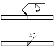
Can some tell me whether the Bevel Groove Symbol can be turned around or is just one depiction no matter which way the Bevel Side is on?
Parent - By Lawrence (*****) Date 09-12-2013 20:10
Typically the arrow is "broken" and points to the side that requires preparation when a specific side is required.
Up Topic Welding Industry / Inspection & Qualification / References on prints

Powered by mwForum 2.29.2 © 1999-2013 Markus Wichitill