Not logged inAmerican Welding Society Forum
Forum AWS Website Help Search Login
Up Topic Welding Industry / ASME Codes / Throat size tolerance
- - By Boon (**) Date 08-05-2013 16:28
In ASME code, is concavity on front side of fillet weld acceptable?
If acceptable, what would be the tolerance value, if any?
I did a search on concavity but could not find relevant answers.

Example. A lifting lug was welded to a pad which in turn was welded to a large fabricated pipe section. If the pad broke off completely during lifting, and was later found to have a concave fillet weld connecting to the pipe section, could this be considered under design?
Parent - - By 803056 (*****) Date 08-05-2013 21:53
That is why most sets of fillet gages have two ends. One end measures the leg dimension and the other end measures the equivalent throat dimension. The weld sizes is the smaller of the two leg or the throat dimension.

In most cases, the size stated by the welding symbol is the smallest acceptable weld size.

Best regards - Al
Parent - - By Boon (**) Date 08-06-2013 16:29
So acceptable weld would be meeting the minimum weld leg or throat dimensions and not weld profile like concavity.

Very often in fillet weld failures we heard comments like "lack of fusion or penetration". How often this is the case and how can we verify "lack of fusion or penetration"? Send the failed components for lab test?
Parent - By 803056 (*****) Date 08-06-2013 18:25 Edited 08-07-2013 13:23
This is just one more case where the actual discontinuity is not described properly due to the use of nonstandard terminology.

I defer to the standard terminology contained in AWS standards such as A3.0 Standard Welding Terms and Definitions or B1.11 Guide to Visual Examination of Welds. That makes sense to me considering I am in the United States and I am working with AWS standards.

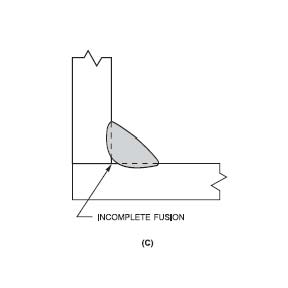
When dealing with fillet welds, there is no "penetration" required, i.e., it is required the weld have fusion to the root, but not beyond to meet the requirements of AWS D1.1's performance test for fillet welds. When the fillet weld does not fuse to the root, it is a case of incomplete fusion, not incomplete penetration.

Joint penetration is the term used to describe a weld where the fusion extends into the joint. I differentiate between groove welds where the weld is in the joint and fillet welds are on the joint (my definition). 

When limiting the discussion to fillet welds, fusion to the root is not usually verified by visual examination alone. One method of verifying fusion to the root of the fillet weld is to section the weld transverse to the weld's axis and polish and etch the cross section to see if there is fusion to the root. Another is to grind the end of the fillet weld to see if there is fusion in the root. In either case, at least a portion of the weld is sacrificed.

Incomplete fusion can be present in other areas of the fillet weld as well as in the root. There may be incomplete fusion at the toe of the fillet weld. We usually refer to that condition as overlap. We can have incomplete fusion at the fusion face where the weld simply does not fuse to the fusion face or simply put, it doesn't fuse to the metal surface because of the presence of oxides, insufficient heat input, etc. In the case of a multi-pass weld, there can be incomplete fusion between the weld beads or the weld layers because of poor weld bead profile, etc.

I hope I answered your question. If not, someone (John, Brent, etc.) will chime in and give us their explanation. Between all the responses, one or more should clarify the situation for you.  

Best regards – Al
Parent - - By welderbrent (*****) Date 08-06-2013 19:33 Edited 08-06-2013 19:41
I would only add this to Al's very informative, accurate, and detailed response...

You started by asking rather the concave weld profile was acceptable (my paraphrase).  To which I say that it is as long as it meets the measurements required by the engineer.  If he/she called for a 5/16" fillet weld we would usually say it would be a convex weld with legs at least 5/16" long measured from the joint to the shortest toe of the weld.  But, if the welder happened to get a concave fillet instead of a convex then we use the other part of our gauge to make sure the throat is of the proper dimension to equal the strength called for by the 5/16" fillet weld. 

So, if the weld in question had a throat of the proper dimension to qualify as acceptable to the job specs then that in itself is not a factor in the failure.  Now, if the engineer underdesigned the weld then it was not large enough but that is not the welder's nor the inspector's problem.  That is an easy check to verify.

If the problem was lack of fusion/penetration into the parent metals that is easily determined as well.  Did it rip or just peel off with one surface having no indications of fusion?  What welding process was used?  Did someone try to use short arc where it should not have been used?  How about weld position?  Was it welded vertical DOWN?  That would also have resulted in a concave profile more than a convex one.  And that would also account for a 'lack of fusion' or better, incomplete joint penetration.  Welding downhill is often done fast and hot which but not necessarily deep penetrating.

There are lots of ways to go if someone is trying to affix blame or make excuses as to it wasn't their fault.  But the fact that it was concave instead of convex in profile is not an indication of a discontinuity that would have precipitated a failure.  Only that it needed to be thick enough through the throat to give the engineered strength. 

A GUESS based upon the very limited information presented: someone welded vertical down around the pipe and while the legs were long enough the throat wasn't so we have a double issue- undersized weld with incomplete joint penetration.  A formula for failure.  But the profile of the weld was not the problem.

Have a Great Day,  Brent
Parent - - By 803056 (*****) Date 08-07-2013 13:34
I like where Brent is headed with his response.

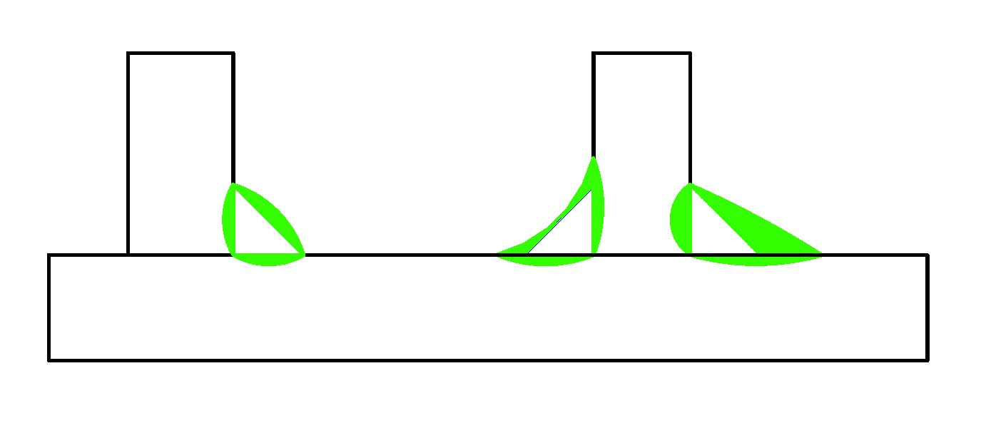
With regards to convex, flush, or concave fillet welds, the thing to remember is: The size of the fillet weld is defined as the largest inscribed isosceles right triangle. With that in mind, the size of the weld is smaller of the leg or throat depending on the contour of the fillet weld.

The standard fillet gage is designed with an isosceles right triangle in mind. If the fillet weld is a perfect right triangle with both legs of the triangle equal to each other, the throat would be equal to 0.707 times the leg. Put another way, either leg would be equal to 1.414 times the throat. So, both ends of the standard fillet gage would measure the weld size as being the same when measuring the isosceles right triangle.

Take that isosceles right triangle and draw a fillet weld so the triangle is inside the fillet weld you just drew and the (now) inscribed right isosceles triangle defines the actual weld size. As shown in the sketch, all three fillet welds are the same “size.”

Best regards - Al
Parent - - By jwright650 (*****) Date 08-07-2013 13:49
Also when looking at the acceptable weld profiles in AWS D1.1 Figure 5.4 and subsequent Tables 5.9 "Fillet" and 5.10 "Schedules C and D", it gives a convexity dimnension (C), depending on the size of fillet,  there is a maximum dimension and all show a minimum dimension of "zero".

Therefore the way I see it....if the minimum allowable convexity is "zero", then no concavity is permitted.
Parent - - By 803056 (*****) Date 08-07-2013 14:17
Hello John;

Two points;

The first would be that this was posted in regards to ASME, so AWS D1.1 does not apply.

The second is that a concave fillet weld is depicted in the top left hand corner of Figure 5.4, page 216 of D1.1:2010 as a desirable profile. Convexity would be zero (no negative dimensions) since convexity is the positive dimension between the convex face and a line drawn between the weld toes. No limits are provided for concavity other than the inscribed isosceles right triangle must be of sufficient size to meet the size requirement. 

I would hate to think we could no longer accept full sized fillet welds because they have a concave contour. Concave contours are preferable when the welds are subject to fatigue. Clause 2.21.6.6 refers the reader to the commentary (C-2.21.6.6) for methods to improve fatigue resistance by enhancing the weld contour: "The desired profile is concave ...."

Best regards - Al
Parent - - By jwright650 (*****) Date 08-07-2013 14:44
Al, I know AWS D1.1 isn't the code to reference here in this thread, I was just adding food for thought about weld profiles.

I was surprised to see that "C" dimn shown as zero, but it is referencing the inscribed triangle as you noted.

...the earlier editions of D1.1 have a much simpler Figure 5.4....I think they muddied the waters when including all of this information in Figure 5.4 and then adding two extra tables.
Was all of that really neccessary to show acceptable profiles?
I have been using the old pre-2010 Figure 5.4 for long, long time and never had any problems with it...why the change?
Parent - By 803056 (*****) Date 08-07-2013 15:11 Edited 08-07-2013 15:17
I agree. I miss the familiar sketches, but once you become accustom to the new figures and Tables 5.9 and 5.10, the level of detail is much better with regards to specific joint configurations and weld sizes, i.e., there less "one size fits all" requirements. One must still read the profile requirements of clause 5.24.

After all these years, considering the fact that the evaluation of the weld profile is part of the visual examination, you would think the committee would combine the profile requirements, associated figures, and tables with the visual criteria of Table 6.1.

Maybe we should pool our resources and take the committee out for some strong drink so we get them to agree to develop a code that is more cohesive and less, how do I say it, like trying to follow a football that is bouncing randomly from one page to another to determine the visual acceptance of a weld.

All I can say is ASME codes are worse. I guess we should thank our lucky stars we have what we have.

I know it is fun to throw stones at these code committees, but having sat in many committee meetings, I know how frustrating it is to get a majority to agree to anything. At best, our codes are a composite of many conflicting opinions. It is a wonder how a group with diverse interests can agree to anything. 

Best regards - Al
Parent - - By welderbrent (*****) Date 08-07-2013 15:12
To give the code committee something to do and the editors something to change so they could charge us for a new book that wasn't really needed???

Have a Great Day,  Brent
Parent - By jwright650 (*****) Date 08-07-2013 16:06
LOL @ Brent's comment.
Parent - - By welderbrent (*****) Date 08-07-2013 14:13
Al, I'm going to steal your attachment for use with training classes at Section meetings.

John, I don't have my 2010 in here at the job since we are working to 2006 on this one, I do have my 2008 and I'm not understanding the way you are wording your last sentence.  Somehow it doesn't compute (of course we know how I am with computers :confused: ).

Have a Great Day,  Brent
Parent - - By 803056 (*****) Date 08-07-2013 14:20
You can send the royalty checks to "Keep Al out of the Poor House"

Best regards - Al
Parent - By welderbrent (*****) Date 08-07-2013 14:31
:lol: :lol: :lol:

Have a Great Day,  Brent
Parent - - By jwright650 (*****) Date 08-07-2013 17:39

>Example. A lifting lug was welded to a pad which in turn was welded to a large fabricated pipe section. If the pad broke off completely during lifting, and was >later found to have a concave fillet weld connecting to the pipe section, could this be considered under design?


I now understand that the welding process used was GTAW.

I'm curious what size fillet weld the designer used on his drawing to weld this lifting lug to the object being lifted(pipe)?
I'm thinking along the lines of the fillet weld size wasn't sufficient for the amount of weight vs a concave fillet weld being the blame. Sounds like the fillet weld was a single pass....was it also welded on the other side of this lifting lug or was just a single fillet weld doing all of this work. Welding one side only isn't a good idea if there is any prying in the weak direction while lifting.
Parent - By welderbrent (*****) Date 08-07-2013 18:09
And they wonder why we usually start off by asking 101 additional questions to get more info than originally provided. 

Every little thing can make a major difference in how we speculate and offer our opinion on the subject. 

Have a Great Day,  Brent
Parent - By Jovi Zhu (**) Date 08-10-2013 02:59 Edited 08-10-2013 03:03
Interesting discussions~

Boon,

To my knowledge for most fillet welds we daily encounter, an as-welded slightly convex contour is often prefered and sufficient without further finishing. For certain instance it is even better and required by the designer to obtain a concave contour by postweld finishing with the weld size guaranteed. The reasonable concavity further mitigates the stress raiser near the weld toe. If that fillet weld is to join something in your kitchen, you don't want the convex weld giving you a hard time cleaning the weld toe, right?

However, it is less prefered to directly get an as-welded concavity, as the solidification process of a concave weld will form a higher stress concentration at the weld face center compared with that of a convex one.

So...the concavity per se should not always be consider as unacceptable. when a designer indicate a concave contour symbol with a "G" on the drawing, it's never his intent to creat a defect/flaw.

Cheers,

Jovi
- - By Boon (**) Date 08-07-2013 17:11
Thank you for very informative comments.
Just a few points.
The welding process with concave weld is GTAW. I have never seen SMAW process with concave profile before.
Also noted that Al uses the term incomplete fusion, not penetration but Brent uses the term penetration.

Regards
Boon
Parent - By welderbrent (*****) Date 08-07-2013 17:24
Boon,

You haven't watched the right guy weld with SMAW.  I can give you a concave fillet with 7018 in almost every position.  Especially vertical down (yes, I have a procedure and am qualified to do full pen that way).  Vertical up may be more difficult on smaller fillets, but still doable.  Flat/Horizontal are easy.  Overhead will depend on size and other factors but not bad. 

Has more to do with thickness of material for dissipating heat, and size and amps on the electrode. 

But now, you welded this plate and lug on with GTAW?  I see a failure already.  Not going there.  I'd have to look some of this back over, but really?  GTAW on a lifting lug?  I'd have to really know my welder to let him even think about that.

Lastly, Al is always right.  When you think you know better, remember, Al is always right.  You will notice I included BOTH words in various locations.  Penetration has more to do with joint depth of weld in groove welds.  Fusion with the fusion zone of weld filler metal and parent material.  So, in your fillet welded application, Al is Always Right.

If you haven't put it together yet, look at his name...Al is short for Always and his middle name is Right.  So, Al is Always Right.

Have a Great Day,  Brent
Parent - - By welderbrent (*****) Date 08-07-2013 17:29
PS, I don't care what may be an allowable process per the code you are working to; somethings just work better with certain processes and procedures while others should be avoided like the plague.

Have a Great Day,  Brent
Parent - - By Boon (**) Date 08-10-2013 07:13
I wonder why you consider certain processes should be avoided like a plague for somethings, in this case lugs.

Comparing between SMAW and GTAW processes, would they give the same strength, perform as well when the weld sizes are the same?

What I believe is probably SMAW is more productive than GTAW.

Regards,
Boon
Parent - By welderbrent (*****) Date 08-10-2013 14:21
Most people do small welds with GTAW and have too small of a tungsten and to low output of a machine.  It will not adequately weld the type of application referenced here, unless, as Al stated in a later post, it is on some pretty thin tubing.  But then, if it was that light weight, why would it have broke.  They also are running very small beads that don't carry the kind of heat for depth of fusion since they are running small tungsten.

Another example, GMAW-S, (you asked about my statement which was not solely directed at this threads application).  You are not to use it as a Pre-Qualified on structural and for good reason, it is not adequate for a large percentage of the welds found in the work.  And, even if you get a PQR stating you can do it, most engineers will not accept the process to do their work anyway. 

Same on heavy equipment, I will use GMAW-S on some light materials on a machine, but when doing major repairs on main members I use either SMAW, GMAW spray, or my first choice- FCAW-G.  I'm not going to use GTAW on heavy equipment for MOST of the work I need to do.  Too slow and usually not hot enough. 

All processes are good for a particular application where you need to stay away from some of the others.  Then, on the next job, the ones you stayed away from are the ones you need while the others are the ones you avoid.

None of them is avoided all the time.  But they all have their place.  That's why my shop has SMAW, GTAW, FCAW (both Self and Gas shielded), and GMAW (both short and spray). 

That's also why I have Air Arc Cutting, Oxy-Fuel cutting, and Plasma Cutting.  Not to mention a bandsaw, chopsaw, cut off grinders, and an Ironworker/shear. 

No one machine or process can do everything. 

Specific for your application, without a lot more info, my first inclination would not have been to use the GTAW to weld it.  And that would be a first 'Red Flag' to me when it broke.  That doesn't mean it fit my term of being avoided like the plague because I wasn't there to know ALL the parameters of the application. 

One more, "perform as well when the weld sizes are the same?"  Yes and no.  It will depend upon rather heat input is a factor.  I can weld it faster with SMAW which in most cases is also going to contribute to keeping the heat input down.  And that can, at times, be a consideration.   More productive: most of the time, yes.

Have a Great Day,  Brent
Parent - By jwright650 (*****) Date 08-07-2013 17:31
Again this is from AWS D1.1:2010 so....take that for what it's worth.
Annex "K" definitions:
Fusion. The melting together of filler metal and base metal(substrate), or of base metal only, to produce a weld.
Joint Penetration. The distance the weld metal extends from the weld face into a joint, exclusive of weld reinforcement.

AWS A3.0 Standard Welding Terms and Definitions
Fusion. The melting together of filler metal and base metal, or of base metal only, to produce a weld.
Penetration. A non-standard term when used for depth of fusion, joint penetration, or root penetration.
Joint Penetration. The distance the weld metal extends from the weld face into a joint, exclusive of weld reinforcement.
- - By 803056 (*****) Date 08-07-2013 19:02 Edited 08-07-2013 19:17
Bent;

Thanks for the vote of confidence, but my middle name doesn't start with the letter "R".

By the way, if you want to see a concave fillet weld made with the SMAW process, try E3XX-17 on austenitic stainless steel. The prettiest concave weld you can imagine.

Now, since this is posted under ASME, I can understand lugs and attachments being welded with GTAW, especially if the material is relatively thin or when the material is anything other than carbon or low alloy steel.

Any process can produce a fillet weld with incomplete fusion to the root. It has been the subject for many of my rants. By the way, thinking of that subject and a different post, if welders struggle to get fusion to the root of a T-joint where the dihedral angle is 90 degrees, can you imagine the problems getting fusion to the root when the angle approaches 60 degrees? Sorry, if the welder can't get fusion to the root when taking a Fillet Break Test, he sure as hell doesn't have any better chance if all he qualified on was the grooved plate test. Once again, the difference between the code and reality rears its ugly head. 

As for knowing all the details, we can only offer an opinion based on the information provided. My opinion is always worth exactly what you paid for it.

Al :confused:
Parent - - By welderbrent (*****) Date 08-07-2013 20:14
Not saying you were directing that at me, I do understand the ability to use the process and it's advantage under some conditions.  But in my experience, limited though it may be, it is seldom used for this particular application.  Just caught me a little off gaurd and made me wonder if that wasn't part of the problem.  But, we can't know with any degree of certainty with info provided.  Total speculation on my part.  And you are 'RIGHT' again, my opinion is worth exactly what was paid for it.

As to being right, I'm still not sure, since you stole the 'R' out of my name you must have needed it somewhere.  My Grandmother had two middle names.  For all I know...

Have a Great Day,  B'R'ent
Parent - - By 803056 (*****) Date 08-07-2013 20:27
Never!

I need as many "R's" as I can get so I can learn to speak Spanish with that long "RRRRR" they use when they speak.  Seriously, it was the "RRR's" that gave me so much trouble when I was attempting to learning to speak Spanish.

Al
Parent - - By Jovi Zhu (**) Date 08-10-2013 03:04 Edited 08-10-2013 05:04
Boon,

Your example is interesting too. I'm not a desigher but I seldom saw a design with a pad between a lug and the large pipe. Why not a lug directly on the pipe? I hope it would not be the circumstance that a designer designed a XXXX and when the XXXX hit the fan blame was put on weld contour made by the welders. In this case I would defend for the welder..."Hey, you designed a XXXX. Not me made that stinky":cool:

If you are working on B31.1 (2010) there are design requirements Part 5, Charpter II often overlooked by shop floor people:

121 DESIGN OF PIPE SUPPORTING ELEMENTS
Parent - - By 803056 (*****) Date 08-10-2013 15:25
I've used pads between the pipe/vessel and a lifting lug to distribute the load over a larger area to eliminate the danger of a punch/shear failure. Another application is when the lug is going to be field welded after the vessel is inspected and stamped by the AI. As long as there is no welding directly to the pressure boundary, AI involvement is not required.

When a pad is used and it I welded "all around" I also include a tell-tale hole.

Best regards - Al
Parent - - By Jovi Zhu (**) Date 08-10-2013 16:29
Al,
Thanks a lot for the advice.
I used to work on very heavy pipes and have to confess that I seldom saw a pad designed for lifting purpose. Lugs were often designed with sufficient strength, thickness, quantity, etc... and shop-welded before Code stamping. Some even designed with full penetration groove + fillet.

Anyhow whether a pad design is OK depends indeed on many factors.
Parent - - By Jovi Zhu (**) Date 08-11-2013 04:37
Gentlemen,

You may think this is off topic but I'm reminded of the mechanism of "lamellar tear".

Definition by AWS A3.0 2010:
lamellar tear. A subsurface terrace and step-like crack
in the base metal with a basic orientation parallel to the wrought
surface caused by tensile stresses in the through-thickness
direction of the base metals weakened by the presence of
small dispersed, planarshaped, nonmetallic inclusions parallel
to the metal surface.

I've seen for many times that UT is required on engineering drawing for specific areas of pipe or beam base metal before load-carrying lugs are welded. This is to avoid welding load-carrying attachments on the weakened base metal area due to the presence of small dispersed, planarshaped, nonmetallic inclusions parallel to the metal surface.

So...I'm wondering if the pad design is per se a creation of "weakened base metal.“ Your thoughts~
Parent - By 803056 (*****) Date 08-11-2013 18:24 Edited 08-12-2013 11:20
Given a choice between lug secured with a CJP groove weld with reinforcing fillets or a reinforcing pad with a small continuous fillet all around the pad, I'll opt for the welded pad.

The heavy welds tend to develop lamellar tears more readily that a small weld. D1.1:2010 has some guidance for preventing lamellar tears in clause 2.7.3.  Don't forget the telltail hole.

Best regards - Al
Up Topic Welding Industry / ASME Codes / Throat size tolerance

Powered by mwForum 2.29.2 © 1999-2013 Markus Wichitill