Not logged inAmerican Welding Society Forum
Forum AWS Website Help Search Login
Up Topic Welding Industry / General Welding Discussion / Opinion Poll... MT & Paint
- - By TimGary (****) Date 01-29-2014 04:34
What is your opinion of MT through paint?

Thanks,
Tim
Parent - By 46.00 (****) Date 01-29-2014 05:12
No
Parent - By ctacker (****) Date 01-29-2014 06:44
Paint will adversely effect the sensitivity.
Parent - By Jim Hughes (***) Date 01-29-2014 14:09 Edited 01-30-2014 12:35
Tim,
most MT procedures that I have worked under require the material to be clean of foreign material including paint. Prior to magnetic particle examination, the surface to be examined and all adjacent areas within at least 1 inch shall be dry and free of all dirt, grease, lint, scale, welding flux and spatter, oil, or other extraneous matter that could interfere with the examination. This is typically what we address in our procedures.
Hope that helps.
Jim
Parent - - By welderbrent (*****) Date 01-30-2014 00:42
The following is from ASTM E-709

9. Part Preparation
9.1 General—The surface of the part to be examined should
be essentially clean, dry, and free of contaminants such as dirt,
oil, grease, loose rust, loose mill sand, loose mill scale, lint,
thick paint, welding flux/slag, and weld splatter that might
restrict particle movement. See 15.1.2 about applying dry
particles to a damp/wet surface. When testing a local area, such
as a weld, the areas adjacent to the surface to be examined, as
agreed by the contracting parties, must also be cleaned to the
extent necessary to permit detection of indications.
9.1.1 Nonconductive Coatings—Thin nonconductive coatings,
such as paint in the order of 0.02 to 0.05 mm (1 or 2 mil)
will not normally interfere with the formation of indications,
but they must be removed at all points where electrical contact
is to be made for direct magnetization. Indirect magnetization
does not require electrical contact with the part/piece. See
Section 12.2. If a nonconducting coating/plating is left on the
area to be examined that has a thickness greater than 0.05 mm
(2 mil), it must be demonstrated that discontinuities can be

Have a Great Day,  Brent
Parent - - By 803056 (*****) Date 01-30-2014 02:45
No mention that all the paint has to be removed if indirect magnetization is used.

Al
Parent - - By welderbrent (*****) Date 01-30-2014 05:00
I had just read this as both Darrell and I are prepping (he actually just got his MT yesterday) for MT level II. 

Don't know much else, would have to go back and read it.  Mainly was wondering if the 2 mil thickness was what you stated as 12 mil was in your mind? 

Have a Great Day,  Brent
Parent - By 803056 (*****) Date 01-30-2014 15:30
I read the article many, many years ago. That's why I said, "don't quote me." I remember the number 12 mils, it may have been the thickness at which the flux leakage is reduced to the point where meaningful indications are no longer formed. That being said, there are so many variables involved, I doubt there is any one finite number that works in all cases. A coil shot is a good example. The test piece can be positioned at the center of the coil or it can be placed against the ID of the coil. The field strength varies accordingly. However, as the coating thickness increases, there is less likelihood an indication will form because the flux leakage field has little driving force to cause it to leak to the surface, hence a weak or no indication may form.  

Best regards - Al
- - By 803056 (*****) Date 01-29-2014 23:05 Edited 01-29-2014 23:51
It depends.

Is the item being tested new construction covered by the welding standard or in-service inspection where the construction may not apply (i.e., ASME code sections).

It depends on whether prods, a yoke, or a coil is used.

It also depends on whether wet particles or dry particles are used.

It also depends on whether fluorescence wet particles or non-fluorescing magnetic particles are used.

It also depends on the level of sensitivity required.

If prods are used, i.e., direct magnetism, the prods must make intimate contact with the base metal to ensure good electrical contact is made. If this is the case, the paint or other nonconductive coating must be removed from any surfaces where the prods will make electrical contact with the surface of the base metal.

If a yoke or a coil is used (indirect magnetism), direct contact is not required. However, the thicker the coating or the further away from the test surface the yoke or coil is positioned, the weaker the flux density induced into the part being tested.

The deciding factor is whether necessary flux density and flux leakage is strong enough to form an indication.

There is a paint product sold to improve contrast when testing with non-fluorescing dry magnetic particles. I typical apply a coating of dry developer from my solvent removable penetrant test kit when photographing a discontinuity. I have yet to notice a loss of sensitivity. If anything, the improved contrast increases the chance the discontinuity will be seen.

I have read studies where the paint coating has to be a certain thickness before dry magnetic particles lose the ability to detect discontinuities that are large enough to be categorized as defects. Don't quote me, but 12 mils seems to ring a bell.

In the case of new construction, most welding standards state that the visual examination and NDT is to be preformed before coatings are applied. However, the same requirements do not necessarily apply to in-service inspections. In those cases where the fabricator has applied the coating before VT is performed, the Engineer will often permit MT to be used to verify the presence of cracks and overlap. 

A simple experiment you can try is to make a magnetograph. Take a yoke and lay a piece of paper over it. Energize the yoke and apply dry magnetic particles to the surface of the paper and you can see the lines of flux formed. The magnetic field passes through the air and through the paper to form the magnetic particle indications.

Take two bar magnets and place the North and South poles together. The interface between the poles represent a crack. Lay a piece of paper over the magnets and again, apply the dry magnetic particles to the surface of the paper. Indications will form at the interface between the poles, at each poles (North and South), and along the line of flux passing through air.

Think for a moment of a subsurface discontinuity in a ferromagnetic base metal. If the discontinuity is near surface, an indication can form provided the flux density is sufficient to produce a flux leakage. That is if enough lines of flux are diverted to and breaking the surface of the metal is strong enough, an indication is formed. The strength of the flux leakage  is dependent on the permeability of the base metal, the strength of the magnetizing field, the depth of the discontinuity, and the size of the discontinuity. The thickness of the metal above the discontinuity can be thought of as a ferromagnetic "coating." As  a matter of fact, a nonconductive, nonmagnetic coating will produce a stronger indication than the ferrous metal separating the discontinuity and the surface of the base metal. The ferromagnetic material above the subsurface discontinuity "conducts"  the lines of magnetic flux so they tend not to break the surface of the ferromagnetic material being tested, thus no indication or a weak indication may form.

The "strongest" indication may well form when the surface of the metal is clean, uncoated, and no mill scale is present. However, contrast also plays an important function when performing magnetic particle tests. There are times when paint is present. The report should make note of the surface conditions encountered. The Owner/Engine can then make a decision that the test provided the information sought or additional testing is required after the surfaces are better prepared for testing.

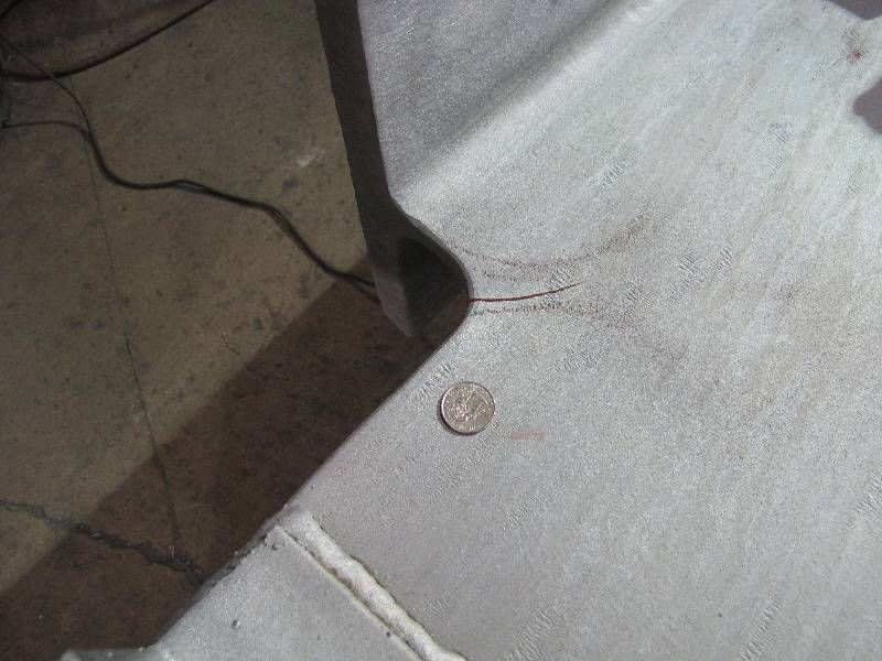
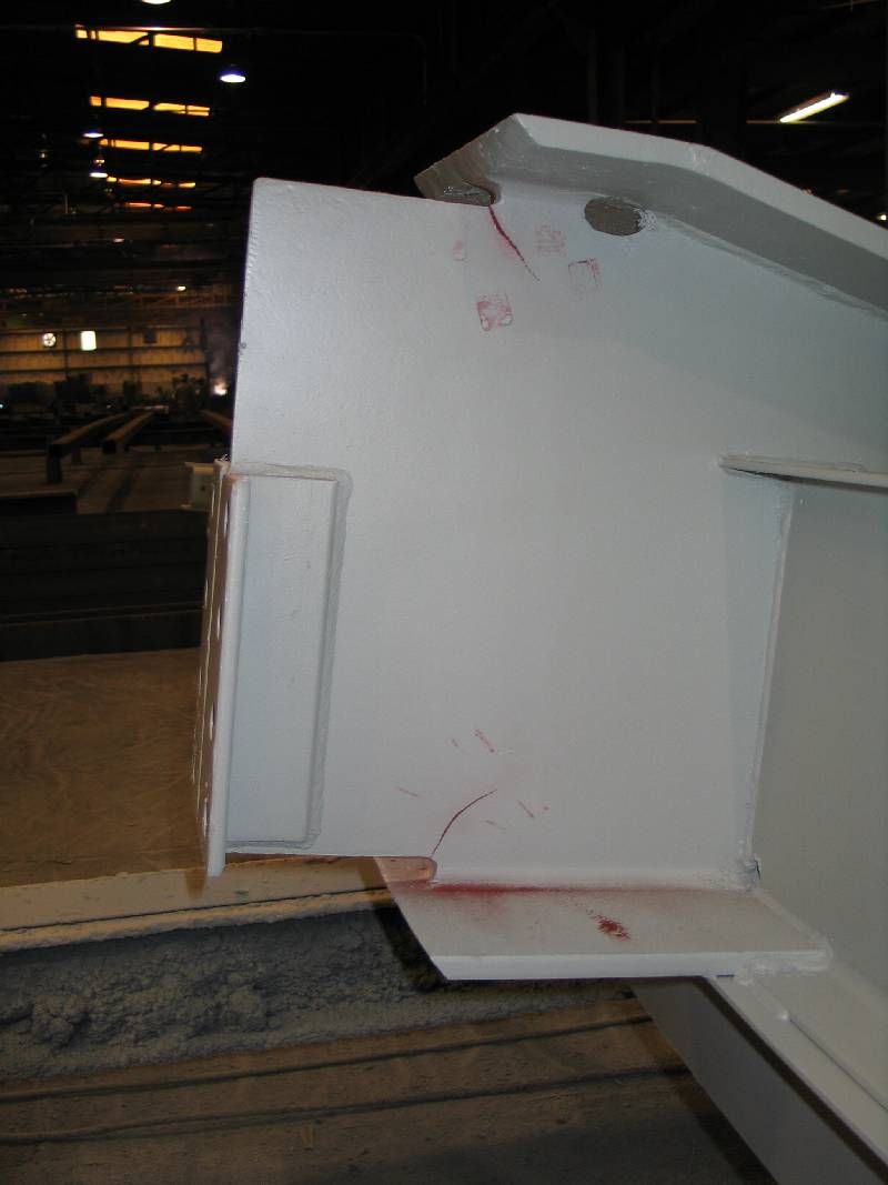
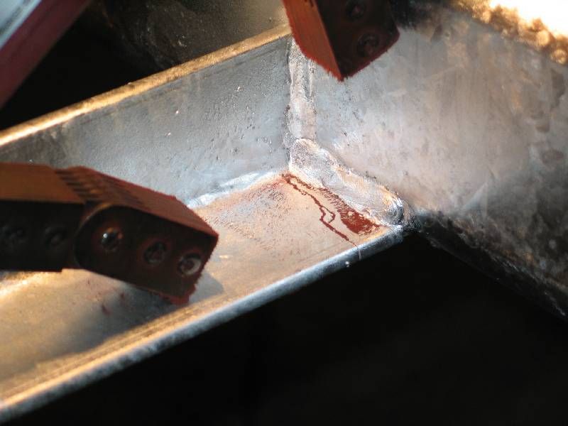
To say one cannot perform MT if the steel is painted is ignoring the fact that it is done everyday quite successfully. The attached photo is a magnetic particle indications on hot dipped galvanized steel. I don't believe anyone can make a reasonable argument the indication is an aberration. HDG: nonmagnetic coating, thickness - variable.

Best regards - Al
Parent - - By 46.00 (****) Date 01-30-2014 01:29
I'm surprised that you have this opinion regards MT on painted surfaces. It does contradict some quite prevalent standards. However, this is is an opinion poll and it is your opinion. I would not choose to accept your arguments in a real life situation and I believe I could quite easily argue against you. I believe there are way too many variables present in your argument.
You do have alot of if's!
Parent - - By 803056 (*****) Date 01-30-2014 02:34 Edited 01-30-2014 04:50
That was one of the points I was trying to make, there are many variables to considered.

Just because there is a shop coat of paint is no reason to eliminate MT as a possible test method. The sensitivity may suffer some degradation, but it will detect many discontinuities that are not obvious to the unaided eye.

I would not use dry particle MT as a means to detect IGSCC, but it works pretty good at detecting cracks under HDG. The crack is often completely concealed by the HDG. John Wright identified an on-going problem with cracks in the area of copes and blocked flanges in A992 structural steel that was HDG.

I believe it is the function of the Level III and the Engineer to assess the circumstances and make a reasonable decision as to what NDT will detect the discontinuities of interest.

Once a problem has been identified, additional costs for further investigations that entail paint removal, other surface preparations, can be justified.

I do a lot of press inspections. They are painted or covered with grease. MT still works perfectly fine for detecting cracks that are completely concealed by paint. That is, the paint is still intact, but the cracks are still easily detectible using MT. In the case of grease and oil, I switch to wet fluorescent magnetic particles after wiping the grease and oil. In those operating conditions, you are never going to get the surfaces perfectly clean, yet the MT works just fine. Often the small cracks are not visible to naked eye, but the MT shows them perfectly fine.  As you can see, I applied developer to improve the contrast to get a good photograph.

The Level III should have sufficient experience and knowledge to understand the limits of the NDT methods available. When there isn't a standard that is applicable, it is up to the Level III and the engineer/customer/owner to determine what is mutually acceptable. Equipment that has been in service is going to develop cracks. The goal of the inspection is to identify areas that are compromised and then to monitor the crack growth over time. If the crack isn't propagating, leave it. The crack is a mechanism that relieves stress. The cracks often remain static for years. Others, propagate. Those are the ones that must be repaired after the root cause has been determined. FEA is often used to determine what the stress levels are and where the stress are highest. In some cases the press frame has to be modified so the mechanism leading to the crack is corrected. MT locates the ends of the cracks long before they are wide enough to fracture the paint.

Sometimes the repairs are unorthodox. I've repaired several presses for customers scattered across the US and a couple overseas. Once I develop an approach, I work with an engineering firm that does FEA to verify the fix will work. I  recognize that I have limitations, I can't do it all. I depend on experts that can do the things that I can't do. Together, as a team, we have been pretty successful in keeping our clients' presses operational. The point is, I use several NDT methods to provide me with the information I need. Much of the work I do isn't covered by codes or standards. NDT is an investigative tool. I am not bound by accept/reject criteria. We know the machines are not in perfect condition. Our task is to determine whether they are safe to continue operating or whether they need to be repaired and then determine how the repair is accomplished.

Best regards - Al
Parent - By jwright650 (*****) Date 01-30-2014 11:15
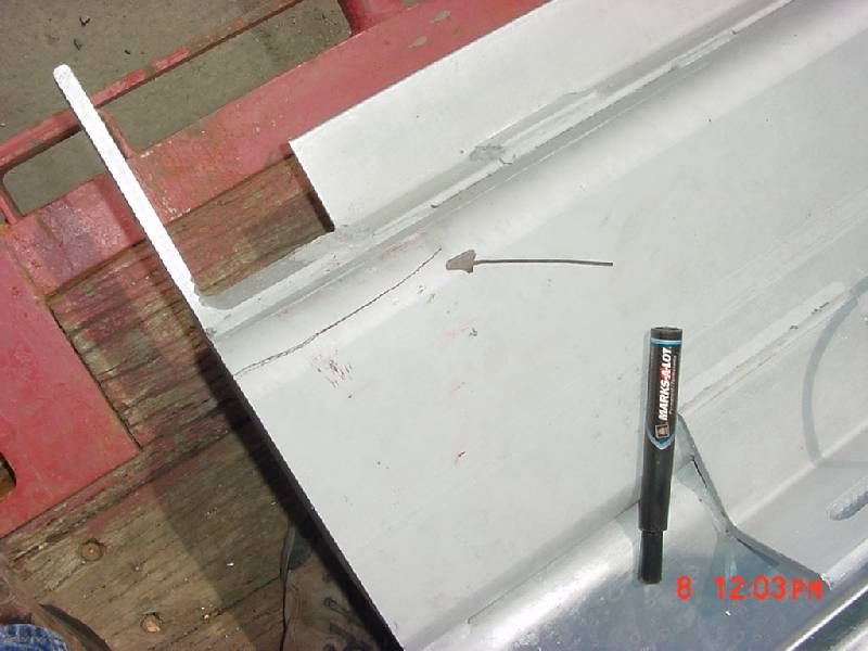
Al, I have been in situations where there were visible cracks in HDG peices and MT verified the extent of the cracking for the shop to gouge and reweld....yes, it does work through coatings.

If you have control over the situations, maybe you can influence someone to leave the coating off around the area of inspection, but that is a tough situation after the fact.
Parent - - By jwright650 (*****) Date 02-01-2014 14:21 Edited 02-01-2014 14:43
Here is a pic of HDG as Al described...nothing was visible until the powder found the flux leakage.


Here is another that was HDG and Painted....shop didn't know that I was planning to MT this piece and they painted it. I managed to catch it before they loaded it onto the truck.


another

Here is a HDG piece of TS 6x6x5/8 that has a sawed end and the crack was along the radius of the TS.


Here is a HDG frame maded out of angle....the cracks were over in the base material.


Parent - - By 803056 (*****) Date 02-01-2014 15:23
Thanks for the photos John. I was starting to feel like a lone wolf.

Best regards - Al
Parent - - By jwright650 (*****) Date 02-01-2014 15:27
RE:The pic of the HDG and Painted
I don't know right off hand the number of mils of coating on this piece but I'm sure it was significant.
It had HDG, a primer, and then an epoxy coating applied to it.
Parent - - By 803056 (*****) Date 02-01-2014 16:08
I can guarantee it was more than 2 mils!

Best regards - Al
Parent - - By welderbrent (*****) Date 02-01-2014 17:08
Sounds like the bottom line comes down to the engineers opinion and stated directions for his/her job.  As usual the responsibility and method along with acceptance/rejection criteria will ultimately be under their direction. 

But, as I am currently studying this, I sure appreciate all the input.

Have a Great Day,  Brent
Parent - By 803056 (*****) Date 02-01-2014 21:00
Just keep in mind some codes apply to new construction only. If that is the case, the Engineer should be defining the conditions, procedures, and criteria to be applied to in-service inspections.

Best regards - Al
Parent - - By Smooth Operator (***) Date 02-02-2014 00:37
Why so many cracks showing up in the "cut and copes" on the beam webs?????????? Looks like they were cut and radiused cleanly!!!!!!! What's your opinion why this is happening ......... And the TS6x6x5/8" NEVER seen that or would be looking for something like that......Interesting pictures to say the least.......
Parent - - By 803056 (*****) Date 02-02-2014 16:33
Personally, I believe it is due to Martensite that results from the thermal cutting operation. The code calls for the cut surfaces to be ground back to bright metal (paraphrased) when working with ASTM A992. HDG includes a pickleling operation in hot acid. Acid has an abundance of hydrogen ions that can diffuse into the steel and do its dastardly deed with the hard, brittle Martensite. The residual stress along the cut edge are tensile, exactly what is needed to trigger a crack as the material attempts to relieve the residual tensile stress.

That's my thoughts on the subject.

Best regards - Al
Parent - - By Smooth Operator (***) Date 02-03-2014 02:40
Al, very informative , so in a blast and paint/ hand clean and paint this problem rarely occurs???? And with hot dip , cleaning to a bright metal finish you can alleviate this problem.........
Parent - By jwright650 (*****) Date 02-03-2014 03:50
The first time that I saw HDG and cope cracks was somewhere around 1999/2000. We had a satellite shop and they used a different galvanizer than we did that was closer to them and a truck load of W24x104's came back cracked. One of the W24x104's was 30feet long and it had a crack that started in the cope and went down the web for approximately 24 feet and the top flange was flopping in the breeze. Crazy, I tell ya. Smooth copes that were ground and radiused nicely. We called the AISC and they recommended that we gouge out the cracks and weld them back up, then run a bead around the cope on both sides of the web. Set them back to the galvanizer and they cracked right through the beads that were placed around the copes. We drilled them and then finished the cope with the torch, ground them up and set them to the galvanizer and they also cracked. It seems to come in spells, as I have seen truck loads without any issues and them truck loads where every piece had cracking.
Parent - - By jwright650 (*****) Date 02-03-2014 03:38

> I believe it is due to Martensite that results from the thermal cutting operation.


That may explain a few of these but how about the TS that was sawed, not flame cut. Then there was an angle that cracked across the heel. Those copes were ground after cutting so the formations or any surface cracking should have been ground away. I saw way too much of it to let pieces go out the door without at least checking them in the high probability places.
Parent - By 803056 (*****) Date 02-03-2014 04:05
Martensite can occur as a result of cold work. It can be a problem when cold working austenitic stainless steel. It seems reasonable that if the low alloy steel is rolled at too low a temperature or cold formed, high hardness can be a by product. Hence, there would be or could be a greater susceptibility to stain hardening and a potential for hydrogen assisted cracking.

Just a thought.

Al
Parent - - By TimGary (****) Date 02-03-2014 13:26
Thanks Guys, I appreciate the input.

My curiosity about the subject came about by the need to due some toe cracking failure anaysis in painted and primed steel.
When I was told the welds were to be inspected with MT through the paint, I rejected the procedure.
While I know this can be done sucessfully, results will vary depending on variables such as coating thickness and joint geometry, and finite defects may be missed all together.
I didn't reject the process because it can't be reliably done, but becuase we had no approved procedure in place to regulate the process.
After seeing your replies, I feel comfortable in making the decision.

Thanks,
Tim
Parent - By 46.00 (****) Date 02-17-2014 18:39
If your working to AWS D1.1, this para will apply

5.30.2 Cleaning of Completed Welds.
Slag shall be removed from all completed welds, and the weld and adjacent base metal shall be cleaned by brushing or other
suitable means. Tightly adherent spatter remaining after
the cleaning operation is acceptable, unless its removal
is required for the purpose of NDT.Welded joints shall
not be painted until after welding has been completed
and the weld accepted.
- By lo-hi (**) Date 01-30-2014 01:52
I  have been doing repair work on equipment were the crack was obvious and  through the grinding process magnetized the iron fillings. The rest of the cracks showed up like a chia pet and the paint was fine. Have also seen it through a layer of oily crud. Actually would direct my sparks toward where I thought there might be a problem, and decide if I needed to bust out the carbon.  If I were doing an official inspection, I would want everything clean as can be.
Up Topic Welding Industry / General Welding Discussion / Opinion Poll... MT & Paint

Powered by mwForum 2.29.2 © 1999-2013 Markus Wichitill