Not logged inAmerican Welding Society Forum
Forum AWS Website Help Search Login
Up Topic Welding Industry / Inspection & Qualification / Question on API 1104 Burn-Through
- - By pham Date 06-30-2015 15:06
Hi everybody, I am studying the API 1104 codebook and I am confused on this part and I need your help!

9.3.7.1  A burn-through (BT) is defined as a portion of the root bead where excessive penetration has caused the weld puddle to be blown into the pipe.

9.3.7.2 For pipe with an outside diameter greater than or equal to 2.375in., a BT shall be considered a defect should any of the following conditions exist:

a. The maximum dimension exceeds 1/4 in. and the density in any portion of the BTs image exceeds that of the thinnest adjacent parent material.
b. The maximum dimension exceeds the thinner of the nominal wall thicknesses joined, and the density in any portion of the BTs image exceeds that of the thinnest adjacent parent material.
c.  The sum of the maximum dimensions of separate BTs whose image density for any portion of the BTs exceeds that of the thinnest adjacent parent material and exceeds 1/2 in. in any continuous 12 in. length of weld or the total weld length, which ever is less.

My question is what do they mean by maximum dimension? do they mean the "height"? length? width? of the burn through or do they mean the BT and the parent metal altogether??  Thank you very much :D
Parent - - By jarsanb (***) Date 07-01-2015 12:47
To help understand, I've attached a couple images. keep in mind that burn-through is not excessive penetration in API 1104. Burn through results in a depression, almost a crater, on the pipe I.D. surface. This is a result of burning through a thin root pass area while depositing the first fill pass (hot pass), and the molten metal sucks back into the pipe wall in that area. Common to downhill processes.
Attachment: Burnthrough.pdf (89k)
Attachment: Excessivepenetration.pdf (88k)
Parent - - By pham Date 07-01-2015 18:16
That really clears things up, thank you! :grin:
Parent - - By 803056 (*****) Date 07-01-2015 22:12
Keep in mind the acceptance criteria is for radiographs, not VT.

Al
Parent - By jarsanb (***) Date 07-03-2015 13:27
I've heard that from others as well. I've also been involved with discussions where some have stated that the entire section 9 of API 1104 only pertains to RT. When reviewing API 1104 20th or 21st edition as a stand alone document:

9 Acceptance Standards for Nondestructive Testing
9.1 GENERAL
The acceptance standards presented in this section apply to imperfections located by radiographic, magnetic particle, liquid penetrant, and ultrasonic test methods. They may also be applied to visual inspection. Nondestructive testing shall not be used to select welds that are subjected to destructive testing in accordance with 6.5.

But it's usually not a stand alone document. 49 C.F.R. 192 or 195 is in play more often than not. When it is then API 1104 section 9 is required for VT criteria.

49 C.F.R. 192.241 - Inspection and test of welds.
(c) The acceptability of a weld that is nondestructively tested or visually inspected is determined according to the standards in Section 9 of API Standard 1104 (ibr, see ยง192.7).

Not all joints are non-destructively tested in addition to VT. If the inspector has access to the root of the joint then the expectation is that VT shall be performed on the I.D. Although this section refers to "BT image", and one could argue that VT is impossible without a radiograph "image" per the listed criteria. That would be a very hard sell to regulators in my area. I'm pretty sure they would reference the UT thickness gauges that all our inspectors are required to carry and ask why we didn't verify wall thickness with those or take a physical measurments since we'd be at an open end or pre-fab where VT on the I.D. would come into play. Others may have had different experiences than mine explained here.
Parent - By thirdeye (***) Date 07-09-2015 19:06 Edited 07-09-2015 19:09
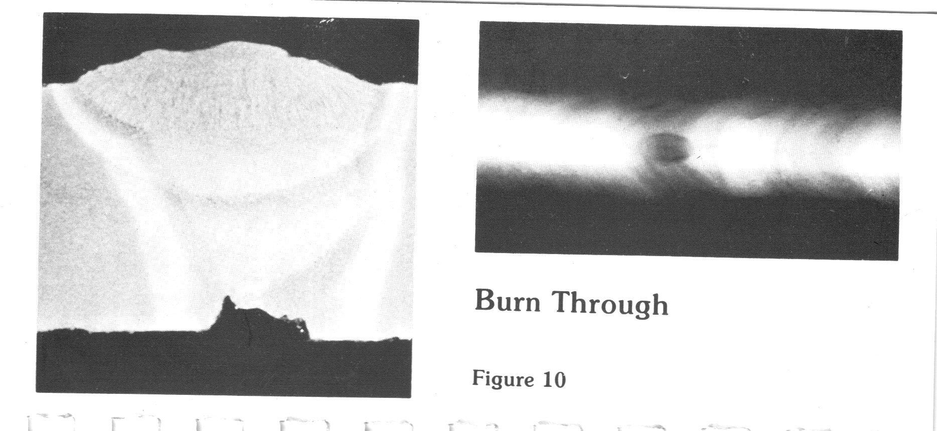
In addition to the photos provided by jarsanb, I've attached another below that shows an actual cross section view of a burn through instead of a sketch.   9.3.7.1 is a little deceiving as it relates to the cause of a burn through.  The molten puddle of the root pass is blown into the pipe leaving a hole or "window".  And excessive penetration is sometimes occurring prior to the formation of a burn through, but it does not always have to be present.  An improper gap (too wide), rod angle or machine setting can also cause a burn through.  I have seen pipeline root pass welders running straight polarity (electrode negative) and the penetration is so shallow it's easy for the keyhole to just blow out, causing a burn through.  They might leave several burn through areas for the hot pass welders to deal with.  As jarsanb mentioned, a repair in this area may lead to a concavity (suck back or suck up).  One difference between a burn through and a concavity is that a concavity is still fused at the sides and the puddle is drawn back below the inside surface of the pipe, a burn through is a more violent condition.

Regarding dimension, radiographs are two-dimensional only, length and width.  Depth (height) can only be estimated based on the density of the indication compared to the density of the adjacent pipe.  So the Code considers measurements in either direction as ground for acceptance or rejection.

Up Topic Welding Industry / Inspection & Qualification / Question on API 1104 Burn-Through

Powered by mwForum 2.29.2 © 1999-2013 Markus Wichitill