Not logged inAmerican Welding Society Forum
Forum AWS Website Help Search Login
Up Topic Welding Industry / General Welding Discussion / Ped bridge in Fla
- - By jwright650 (*****) Date 03-15-2018 22:50
Wonder what happened to that brand new bridge?
Parent - - By 803056 (*****) Date 03-16-2018 04:17
It looked like it was cast in-place concrete that was moved from the sideline into the final position. One would assume they allowed the concrete to cure before moving it, so perhaps it was the placement of the rebar.  Perhaps they save a good deal of money on the inspection.

Tragic some people had to die because of someone's incompetence.

Al
Parent - By jwright650 (*****) Date 03-16-2018 10:56
I feel sure that Fla's DOT had some oversight in the construction of that bridge. Around here VDOT has their hands in everything to some degree when it comes to anything related to the highway.

On a side note....What do they use for aggregate in Fla? Curious because the readymix plants around here use quarries where the stone has high densities. I'm assuming that there are no quarries in Fla.
I've been making compressive strength cylinders(4x8) recently that have been breaking over 10,000 psi for 4,000 psi mix design.
On the 3 day break they have already reached the 28 day design strength. This was for transformer pads in substations and the transformer was due to arrive soon after the pour.
Parent - - By jwright650 (*****) Date 03-16-2018 11:41
Hmm, I wonder if the missing parts had a role in the collapse? Where is the center pylon and pipe supports?
Parent - By Northweldor (***) Date 03-16-2018 14:52 Edited 03-16-2018 15:17
Apprently, they (engineers) were doing a "stress test" without the center pylon installed, and they had ordered "cables" to be tightened. The report below, and another from AP, say no one knows what the engineers were using for center support, but I did see one pic before collapse, and it looked like a crane on the median. See video posted by Steelslinger,  below.

https://www.ctvnews.ca/world/fallen-bridge-stress-test-preceded-collapse-that-killed-6-1.3845565

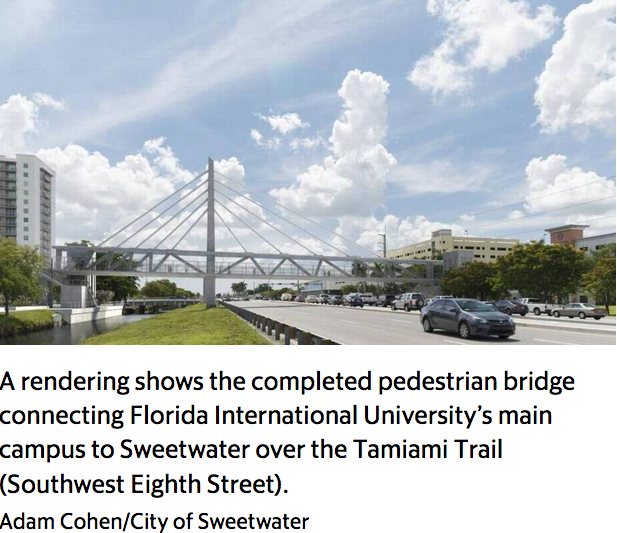
Here is a walk-thru simulation of the bridge, and you can see what it should have looked like!

https://www.cnn.com/2018/03/15/us/fiu-bridge-collapse-accelerated-bridge-construction/index.html
Parent - - By Steelslinger (**) Date 03-16-2018 12:41
Here's a video of the collapse.

http://www.miamiherald.com/news/local/community/miami-dade/article205443304.html

John, I would suspect that will be a huge contributing factor.

Also, as I am not as familiar with concrete span construction, how common is it to move that long of a concrete span as a single piece? Wouldn't the stress of moving something like that lead to development of fractures?
Parent - - By 803056 (*****) Date 03-16-2018 18:47
The fact sheet indicated it was a post tension design and they were retensioning some of the cables. Usually the cables are tensioned after the concrete is cured to a point. The idea of post tensioning the cables is to place the concrete in compression. They may have been initially tensioned, but not up to their final tension. At this stage, it is still too early to know exactly what the chain of events were.

A lot of post tensioned structures are in service and perform rather well and without notice by the general public.

Al
Parent - - By Northweldor (***) Date 03-17-2018 00:12
The fact that they are installing the span without the central pylon in place seems very odd. Most of these bridges get their main support from the central pylon.
Parent - By 803056 (*****) Date 03-17-2018 00:21 Edited 03-17-2018 04:44
It looks like the bridge had another 110 ft section that would have been to the left of the span that collapsed. The central pylon would have been in the median under the left end of the span that collapsed. It tough to tell exactly since I have not seen a definitive drawings or sketch that shows exactly what the final bridge design looked like. The details provided so far are rather sparse. Evidently the span that was erected was supposed to be self supporting until the pylon was constructed and stays placed. Oops!

Al
Parent - By ipcbridge Date 11-15-2018 07:11
Yes, I like your great topic. we offer The prestressing steel cables inside the sleeves or plastic ducts are positioned in the forms before placing the concrete post tension tendon.
- - By 803056 (*****) Date 03-17-2018 14:44
Here is a link to a website with more information or at least a couple of videos and a good sketch of the bridge once completed.http://www.miamiherald.com/news/local/community/miami-dade/west-miami-dade/article204506084.html#0

It is a post tension stayed bridge. I guess they thought the span was stout enough to support its own weight until the tower and stays were placed. 930 tons is a lot of dead weight. Once in position the lower deck would be in tension while the upper deck would be in compression without the stays in place. The diagonal web members would be in tension or compression. The loads could be enormously high in the web members and without sufficient rebar to transfer those loads into the top and bottom decks, the diagonals could punch through the decks and collapse.

The nature of the loading could also be change dramatically once the stays are in place and tensioned.

As mentioned, it is too early to know with any certainty. There was a peer review performed by third party engineering firm from  what I've read. That is pretty standard practice, but whether it was a review of the bridge after completion or during erection wasn't clarified.

It would be reasonable to assume the erection plan would consider the dead load of the span during erection and its stability until the stays were placed. However, from the video, it appears the collapse was sudden and  with little warning to those working on it.

They say there was a voice mail stating there were cracks observed, but I didn't hear where the cracks were seen. Transverse cracks in the lower deck could be expected since it would have been loaded in tension. The post tension cables are designed to carry the tensile stresses. Concrete in tension is not very efficient. That's why rebar are placed where the tensile forces are developed. However, whether the tension cables were designed to carry the dead load of the entire span without the stays in place is another question that has to be reviewed and answered.

As mentioned earlier, the diagonal web members are in tension or compression both during the erection phase and once the bridge was completed, but the nature of the loading could be changed once the stays are in place. The magnitude of the loads in the diagonal web members would be altered significantly once the stays were in place. That leads to the question whether the forces developed by the diagonal web members at the connections with the upper and lower decks were appropriately accounted for. Without proper reinforcing, there could have been a punch through failure at the connection of either the upper or lower decks.

It would not be surprising to learn the root cause was a failure in communication between the different parties involved. The designer designed the bridge and sized the members based on the loads anticipated when the bridge was complete. A different group considered the means and methods of erection. Whether the lines of communications were open and efficient is something that would need to be checked. A failure to communicate has been a problem in the past where structural failures were involved. Think of the the walkway in the Tea Room collapse.

Due consideration must be given to the changes in loading during transportation, temporarily before the stays are placed, and once the bridge was completed. That would include supporting the span as it was moved from the sideline where it was constructed to its final position on the piers. The loads would change because of the location of the supports during transportation and the location of the supports once the span was placed in its final location on the piers. During transportation the supports were located (from what I could see in the photographs, about 1/4 of the span's length from each end. The portions cantilevered beyond the supports would counter the weight of the spans between the two supports. Once in position on the piers the load is supported at the ends of the span, again changing the nature of the loads. It makes it easier to understand the nature of the loads and deflection of the members if one thinks of the span as a wet noodle. The members flex and deform much like a wet noodle. See  attached sketch.
Parent - - By Northweldor (***) Date 03-18-2018 19:18 Edited 03-18-2018 19:53
The cracks were on the North end, which appears to be the canal-side, next to what would have been the location fore the 106' cable supporting mast pier.

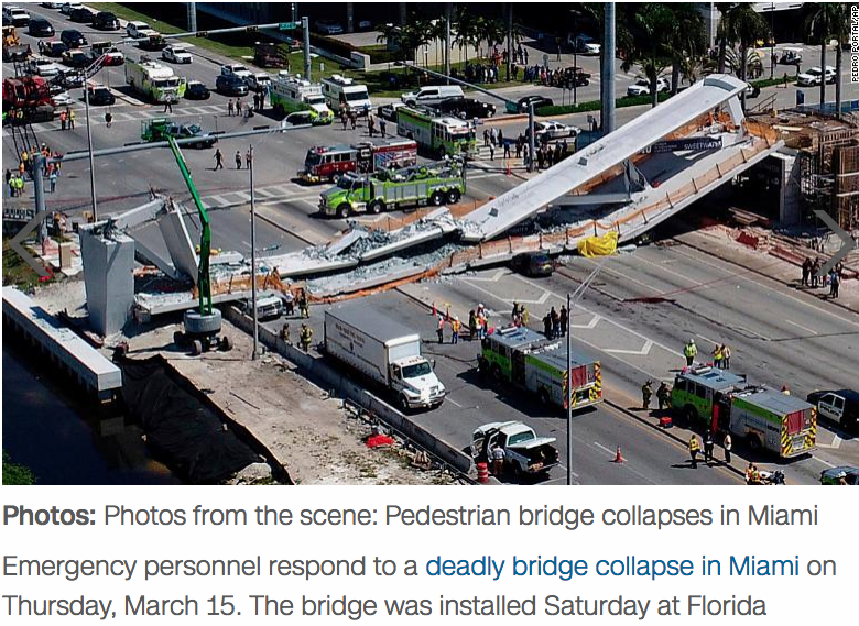
Using your excellent analysis, and a couple of the pictures, a good guess might be that the punch-through failure you describe occurred in the upper or lower deck, just where the first cable on the main-span side would have been attached, at the end of the first web-diagonal.

Here is a collapsed picture of the bridge which shows the top part of the mast pier has been pulled over and a fairly clean break at the end of the first diagonal away from the pier. Also, a rendering of the completed bridge.

If the failure occurred in the lower deck, the other web diagonal may be under the deck, which seems to pulled off the pier. Also, there seems to be a slot in the rubble, where it should have been.
Parent - - By Northweldor (***) Date 03-23-2018 03:17 Edited 03-23-2018 03:31
I think this video and the additional information that the supporting tower foundation was moved to extend the main span by 3 meters on the North end,  shows that Al's and Johns's analysis was correct. The video seems to show a punch-through of the lower deck, and subsequent collapse as a result. Engineering, contracting and oversight heads should roll, on this tragedy!

http://canoe.com/news/world/dashcam-video-shows-terrifying-moment-pedestrian-bridge-collapsed-near-florida-international-university

Note that the only support was the crane on the North end at the lower deck site of the first diagonals!
Parent - - By 803056 (*****) Date 03-24-2018 15:06
The dash cam video is chilling to watch. It appears the failure occurred as soon as the bridge was cut loose from the crane (if one assumes the crane was supporting it.

If the span was transported and hoisted into position by the prime mover (the weekend before the collapse), one must wonder why the crane was needed to support the span. The next question is, how was the span rigged as it was suspended by the crane. I didn't see any spreader beam go flying when the collapse occurred.

Al
Parent - - By Tyrone (***) Date 03-26-2018 11:02
I doubt that the crane was used to support the span.  It didn't move a smidgen when the span fell. No cables or anything.
Parent - - By 803056 (*****) Date 03-26-2018 13:23
You are probably correct. What I thought might be the crane hook bouncing could be debris.

Al
Parent - - By Tyrone (***) Date 03-27-2018 11:19 Edited 03-27-2018 11:23
According to the YouTuber, identified only as AvE, a single snapped tension cable spotted at the site paints a picture of crews negligently trying to jury-rig an unstable bridge while still allowing midday traffic to pass underneath.

By analyzing building plans and construction photos from the site, AvE concluded that the bridge would have been fine as initially designed, but that it was brought down by shortcuts taken on the construction site.

But photos and video from the swing-out reveals that the heavy-lift vehicles used to move the span were positioned differently than indicated in the bridge’s original plans, which would have placed stress on weaker areas of the bridge. This, in turn, could have upset the latticework of cables holding the bridge together.

The “smoking gun” for AvE’s theory is that in footage from the collapse it’s possible to see a tension rod sticking out of the wreckage still attached to the hydraulic cylinder that would have been used to tighten it.

See whole story with pics and video.

http://nationalpost.com/news/canada/random-canadian-finds-the-smoking-gun-in-florida-bridge-collapse
Parent - - By 803056 (*****) Date 03-27-2018 13:58
There are some interesting conversation at eng-tips as well on this subject.

Al
Parent - - By Northweldor (***) Date 03-27-2018 20:27 Edited 03-27-2018 20:32
I wonder why there is no mention of the worker on the top deck at the crane cable location, who gets up and starts to run, but is left in mid-air, as the bridge falls out from under him. If he survived, he probably has an interesting story to tell!
Parent - - By 803056 (*****) Date 03-27-2018 21:55
Isn't that the truth.

Al
Parent - - By Northweldor (***) Date 03-28-2018 16:00
Parent - - By jwright650 (*****) Date 03-29-2018 11:22
I was wondering if they would core the concrete. I suppose they will compress those samples to make sure the concrete had come up to the design strength. Interesting what AvE had to say in that YT video. NTSB seem to follow that same trail by reading that press release of the items that they took back to the lab.
Parent - By Northweldor (***) Date 03-29-2018 23:37
Another problem of Figg engineering, that involved modification of a straight steel construction support  truss, to use on curves.

https://pilotonline.com/news/local/transportation/article_dc3791ef-914e-5794-9b30-9c60d426866b.html
Up Topic Welding Industry / General Welding Discussion / Ped bridge in Fla

Powered by mwForum 2.29.2 © 1999-2013 Markus Wichitill