Not logged inAmerican Welding Society Forum
Forum AWS Website Help Search Login
Up Topic Welding Industry / Technical Discussions / Vertex angel (GTAW) less or more give good penetration
1 2 Previous Next  
- - By Toey TNDT (**) Date 09-20-2014 13:19
Dear all ,
I read welding handbok Vol 2 180 degrees give high penetration but In IWE book 30 degrees give high penetration ( how method i can show my image ) Not CSWIP question. anyone come to clarify
Thanks in advance

Sorry for my mistake language

Regards ,

Toey Tndt .
Parent - - By welderbrent (*****) Date 09-20-2014 16:21
Toey,

Have patience with me please.  I have resisted foreign language for so long in my life, that now as I get older and with technology have communication opportunities with people from other parts of the world it is difficult to communicate having only one language as a base to work from.  Hard to learn now though I totally believe we are never too old to learn.

Now, are we talking temperatures?  I can't see you referring to bevel angle as 180° would not be realistic.  And what type of joint and welding process are we talking about?  It is all these little details that can make a difference.

BTW, use 'ALT' '2' '4' '8' (holding alt as you consecutively hit the numerals) and it will give you °.  You may have to engage your 'NUM LOCK' to make it work.   

Back to topic, if we are talking temperatures, could part of the difference be that one is referring to °F while the other is °C?  From there, it would make a difference in material grade, thickness, and other considerations. 

I'm not really sure what you are asking and just trying to get more info.

He Is In Control, Have a Great Day,  Brent
Parent - By SCOTTN (***) Date 09-20-2014 16:39
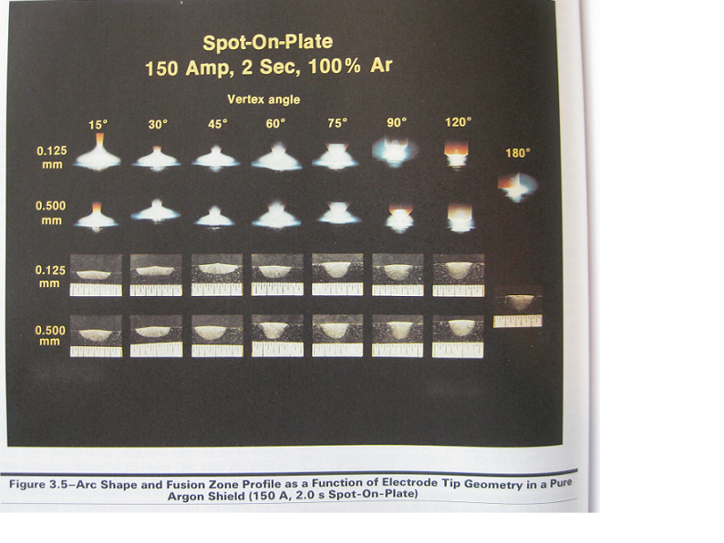
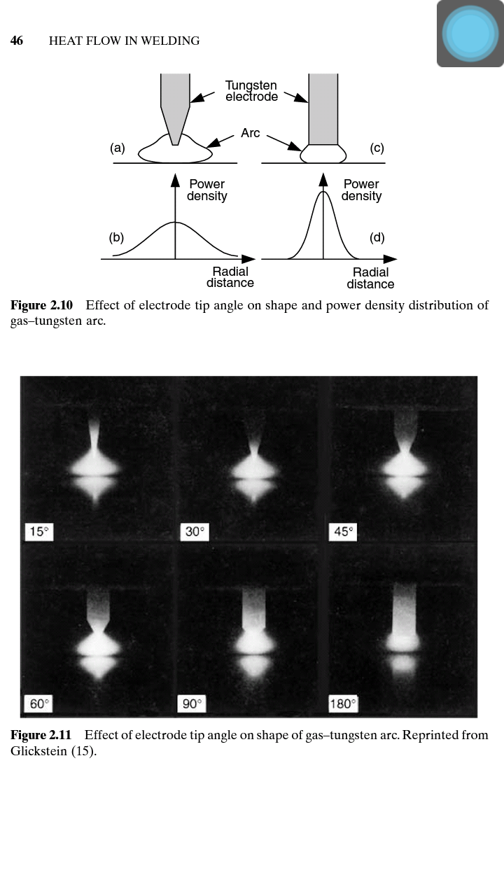
Here's a link to an older article that has a couple photos showing various arc shapes, fusion zones, and gas mixtures, that may be helpful....

http://files.aws.org/wj/supplement/WJ_1980_12_s365.pdf
Parent - - By electrode (***) Date 09-20-2014 18:07 Edited 09-20-2014 18:10
Brent,
I presume the OP is asking on how the included angle of a ground W-electrode may affect depth of penetration.
Regards

EDIT
I should have had a look first at the document behind the link embedded by 'SCOTTN' which is actually answering your question.
Parent - By welderbrent (*****) Date 09-20-2014 20:00
Silly me, goes back to Henry's oration on posting.  How about 'READING'.  If only I had looked closer at the title of the thread.  Thanks guys.  Just ignore me Toey.  Not one of my better posts by any stretch of the imagination.

He Is In Control, Have a Great Day,  Brent
Parent - - By Toey TNDT (**) Date 09-21-2014 01:43
Yes . I will say about include angle .
I belive in Welding handbook but why IWE book shows that 30° give good penetration .
Do you have email . I will send image to you
Parent - By electrode (***) Date 09-21-2014 12:23
Toey,
I suggest to thoroughly read the article behind the link posted by 'SCOTTN' first.
Presumably this is a good start.
Then, in case of lack of clarity, to come back here in order to ask and discuss.
Here's a number of distinguished individuals around; sure they're willing to point you in the right direction.
It would be also interesting to understand what you are thinking on the impact of different vertex angles.
Did you maybe practically experience that different included angles were changing "penetration"?
Parent - - By Toey TNDT (**) Date 09-21-2014 01:50
Brent ,

Thank you for comments

I effort to learn language .

In this case  if i can show image you will understand .

Can i have your FB or email ?

REGARDS ,
Parent - By welderbrent (*****) Date 09-21-2014 13:43
When considering the angle for your question, as electrode points out, there are a good many very educated and informed people here, but I am not one of them for giving you that kind of answer.  We have educators and much more wise users of GTAW than me.  When it comes to the how's and why's of one angle working for penetration better than another I will definitely step aside and defer to others here. 

Scott's article seems to start you down the right path.  I don't know why one resource suggests one angle and another resource suggests another angle.  And there could be other differences that I didn't look into when I skimmed the article. 

Someone will come along and help.  Sorry I confused the issue earlier Toey,  But Scott and electrode got it turned around. 

And don't worry about looking foolish or having a communication problem, many here are able to cross the language barrier easier than I and we do want to be of help to you.

He Is In Control, Have a Great Day,  Brent
- - By Plasma56 (**) Date 09-21-2014 17:53 Edited 09-21-2014 19:45
This of help?

EDIT. I'm not looking to steal a thunder. I'm slow and unorganized. So I opened a book and took a picture.
My first attempt,second, third to post were to large. But it wasn't a race.
All good.

I wish to see "it" to further discussion to how this information could be applied.
Now I have some time.
With changes in technology this mute point of process get over looked. The effects of exibited trunication profiles identify one thing. The blunter the tungsten shape, the easier it is to push an electron from it or attach to it.
So that means, if I have a choice to make, what would I choose? And do I have a reason why?

A blunter tungsten allow the operator to use a lower current value.
A sharper point requires more current. Because of the point I just mentioned this makes sense.

So what is effected in all this, the need for voltage to move an electron.
What effects weld metal composition most, voltage.

When you ask most knowledgable people the question, which gives deeper penetration profiles, most think it the one with a point attached.
Parent - By electrode (***) Date 09-21-2014 18:24
Plasma56,
with all due respect, this is part of the (original) WJ article connected to the link of 'SCOTTN'.
Parent - - By Toey TNDT (**) Date 09-22-2014 00:36
How i put my image .
Parent - - By ssbn727 (*****) Date 09-22-2014 06:16 Edited 09-22-2014 06:24
Toey,

Write and post your query or whatever it is you want to post... Submit the post... Once the post is shown in the forum, go to the bottom of the very same post and look for the word: "Attach" written in blue letters and left click it with your mouse... By doing so, you should now be in a different page titled "Post Attachments" that shows you where to place the file name of the picture you want to post... Underneath the title you will see this:

You can also upload files by dropping them onto the form. (Second Method of posting pictures using copy & paste)

File(s) (max. file size 977k) <<<<<< Do not try to post an image larger than this size if you want the picture to be shown in the thread you are posting from!

[Browse]  No file selected

Caption
[A long rectangular blank bar used to type the Caption as an option]

[  ] Embed (only JPG, PNG and GIF images)

[Upload]

Now choose the file with the photo you want to post two ways... Either Browse your computer by pressing the "Browse" button...And another smaller "File Upload" box will appear that has choices of sections in your computer, and folders to choose from in order to find the photo(s) you seek to post... Or use the (Second Method of posting pictures)... If you choose to use the first method of posting pictures then follow these directions instead...

Select your choice of picture once you have reached the folder that has the picture you are looking for by highlighting it... Then press the [Open] button shown in the lower right corner of  smaller the "File Upload" box in order to place your choice of picture next to where it says: [Browse] and replacing "No file selected" with the file number of the picture you want to post... Don't get lost on me Toey! We're almost finished here! Once you have completed those above mentioned tasks, you are now ready to post after two more steps...

1.) Check the box next to the words: Embed (only JPG, PNG and GIF images) {meaning only those types of image files are allowed to be uploaded and published}...

2.) Now you can press the [Upload] button... What happens next will be the file uploading into the forum, and you can see this where the selection of buttons are located in this page by looking for a number percentage amount gradually increasing until it reaches 100%.. Once the upload is complete, you should be able to see the picture you chose at the bottom of the page you are on... You can confirm that it was posted by going back to the thread of the post you started... If it is showing, then you have succeeded!
Follow the steps I laid out for you to the letter and you will have no problems posting picture from now on... Best of luck Toey.

Respectfully,
Henry
Parent - - By electrode (***) Date 09-22-2014 07:17
Henry,
AWS would be well advised using your explanation as a general instruction here on this forum.
Parent - By ssbn727 (*****) Date 09-22-2014 08:17
Thank you sir! I wouldn't hold my breath but, let's see if anyone that can do that - will take a moment to consider it as well.

Respectfully,
Henry
Parent - - By Toey TNDT (**) Date 09-22-2014 10:02
Henry .
I try to find (post attach ) but in my page not have its please send photos to my email please  . Sittichaikmutnb@gmail.com . Thank you too much for your kind.

Toey Tndt
Parent - By electrode (***) Date 09-22-2014 11:23
Toey,
not sure I do understand, but underneath each of your posts, you should see this 'Attach'; see embedded image below.
You only need to make use then of this function, which will open a new window.
Having this before you I suggest to follow Henry's advice/instruction.
You can browse the image(s) you whish to add on your hard disc and simply upload or embed them.
Don't forget to keep the size limitation in mind.
Then quite normally return to the forum and that was it. Now everyone should see either your attachment or your embedment.
Hope that helps.
Parent - By ssbn727 (*****) Date 09-22-2014 13:13 Edited 09-22-2014 13:23
Toey,

Good job! Now if you want to post the screenshot as an image file, you must first go back from the beginning and repeat the steps to follow in the procedure I laid out for you in a previous post...By doing so, you will discover the mistake or mistakes you made and recognize it so it doesn't happen again... Do you understand? I'll take the answer as a yes...

1.) Okay, so you write what you want to include in the post then you go to press the reply button to publish the post correct?

2.) You made a post that you want to include a picture for everyone to see in that same post correct? Of course you do! If you look carefully at your published post, focus on the lower horizontal bar that has different options written on it (Reply - Edit - Attach - Notify)... Look for the word "Attach" and left click that button...

3.) You should notice after clicking the "Attach" button that you are now in another separate & different web page...

4.) If you did previously follow my original instructions, you would have succeeded in posting the screenshot as an image for everyone to view within your post... So there was something you that you over looked for the image not to appear in your post... Not to worry! This happens a whole lot my friend! In fact, I didn't get it right the first time as I reveal another embellishment of the truth to your eyes:roll::eek::wink:

5.) You should now be in a different page titled "Post Attachments" that will show you where to place the file name of the picture you want to post... Underneath the title you will see this:

"You can also upload files by dropping them onto the form. (Second Method of posting pictures (images) using the drag and drop technique)

File(s) (max. file size 977k) <<<<<< Do not try to post an image larger than this size if you want the picture/image to be shown in the thread you are posting from!

[Browse]  No file selected

Caption
[A long rectangular blank bar used to type the Caption as an option]

[  ] Embed (only JPG, PNG and GIF images)

[Upload]"

6.) Now choose the file with the photo you want to post two ways... Either by Browsing your computer by pressing the "Browse" button...And another then a smaller "File Upload" box will appear that has choices written in 1 column on the left side, of sections in your computer (My Recent Documents, Desktop, My Documents, My Computer, My Network) and, the folders for each section can be found inside the box to the right of the sections column to choose from in order to find the photo(s) or image you seek to post...
Or you can use the (Second Method of posting pictures) that's described in the 1st sentence underneath the title: "Post Attachments"... If you choose to use the first method of posting pictures/images then follow these directions instead... Note: The second method doesn't work too well and is more complicated than the 1st method I am focusing on.

7.) Select your choice of picture once you have reached the folder that has the picture/image you are looking for by highlighting it... Then press the [Open] button shown in the lower right corner of  smaller the "File Upload" box in order to place your choice of picture/image next to where it says: [Browse] and replacing "No file selected" with the file number of the picture/image you want to post... Don't get lost on me Toey! We're almost finished here! Once you have completed those above mentioned tasks, you are now ready to post after two more steps...

8.) Check the box next to the words: Embed (only JPG, PNG and GIF images)<<<{meaning only those types of image files are allowed to be uploaded and published}... If you forget to do this step, your image will not appear in your post!!! Very important step Toey!

9.) Now you can press the [Upload] button... What happens next will be the file uploading onto the forum page you are on as well as the page where the post is shown in the thread... And you can see this happening where the selection of buttons are located in this page by looking for a number percentage amount gradually increasing until it reaches 100%.. Once the upload is complete, you should be able to see the picture you chose at the bottom of the page you still on... You can confirm that the image was posted to the original post found on a forum page that shows the thread where the now upload post is by going back to the thread of the post you started... If it is showing, then you have succeeded!

Follow the steps I laid out for you to the letter again without overlooking one step and you will have no problems posting your images from now on...
Best of luck again Toey.:wink::roll::smile::cool:

Respectfully,
Henry
Parent - - By ssbn727 (*****) Date 09-22-2014 05:21
"What effects weld metal composition most, voltage." Aren't you overlooking some metallurgical factors that will directly influence weld metal composition besides voltage? You know like Time @ Temperature, percentage of dilution, cooling rate and choice of heat treatment are amongst a few right off the top of my head...  Shielding gas or the lack of will influence the composition as well... In other words, environmental conditions related to protecting the weld metal from contamination... Indirectly, voltage does influence weld metal composition, but Time @ temperature has more influence of the weld metal composition, and in combination with all of the other factors I mentioned and any that I didn't post...

All have direct & indirect influence to the eventual, and final weld metal composition based on the primary metallurgical factors involved and how they are manipulated.

Respectfully,
Henry
Parent - - By Toey TNDT (**) Date 09-22-2014 11:29
Please see my attach
Parent - - By electrode (***) Date 09-22-2014 12:01 Edited 09-22-2014 13:29
Where?
Parent - - By Toey TNDT (**) Date 09-22-2014 13:28
Please look again
Parent - By electrode (***) Date 09-22-2014 13:29
Finally overcome.
Congratulation.
Parent - - By electrode (***) Date 09-22-2014 15:42
Toey,
just for getting things started.
I suppose you're heading towards becoming an International Welding Engineer, maybe (note TIG instead of GTAW) passing a TWI course somewhere.
Then I need to ask you, as a forthcoming - approved - highly qualified individual.
Did you have a look at the paper connected to 'SCOTTN's link?
If so. When comparing this, see images below; what is your opinion about the stuff presented to you along with the course material?
After reading KEY's paper; can you still "believe" what's been taught to you?
Are there maybe some doubts caused with you in the meantime?
If so. Good. In my experience there is always a root cause for a specific phenomenon occurring in welding - always.
Some of which can be predicted with high accuracy, some of which cannot - yet.
Some of which again have been scratched at the surface along this thread here ... a few at least.
And it's definitely worth digging deeper. At least from my viewpoint.
So, go ahead please. Share your own thoughts.
Parent - - By Toey TNDT (**) Date 09-22-2014 23:09 Edited 09-22-2014 23:13
I compared about welding handbook and sindu kou are same vertex angle give high penetration .if i choose . I will choose welding handbook .because more imformation than IWE (  i just read only . Don't exam as per commment )
Parent - By electrode (***) Date 09-23-2014 19:52
Toey,
good. Sure you have learned "in spite of us". [1]

[1] Plasma56, 2014
Parent - By ssbn727 (*****) Date 09-23-2014 00:28
Way to go Toey!:roll::twisted::smile::lol::yell::lol::wink::cool:
Parent - - By electrode (***) Date 09-22-2014 06:59
Plasma56,
please don't get me wrong.
I was just trying to-again-point towards the original investigation from KEY.
Nowadays (thanks to-almost-speed of light communication) a picture, statistical evaluation or plot is quickly circulated.
Nothing negative with that so far.
This, as a well-intended stand alone attempt, however, to clarify complex subjects, may cause misunderstanding - except thoroughly explained to its reader/interpreter.
At least in my opinion. Let me try to clarify.
I have taken 2 macro-sections, stemming from the picture embedded by yourself.
The only thing that I did, as I suppose all others did. I had a closer look at the macros plotted and it quite easily became apparent.
Now, here's the question. Which vertex angle results are depicted here?
Sure you'll find it and-hopefully-may know what I mean, but what does that mean to the reader who's maybe just quickly skimming through the picture?
You see my point?
Again, no offence.

PS: I'm under the impression you seem to be a friend of 'welding voltage'. Impressive to learn what 'voltage' in general respect seems capable of.
Parent - - By ssbn727 (*****) Date 09-22-2014 07:16
0.125mm with vertex angles of 75 degrees starting with the left photo and 90 degrees for the photo on the right of those two posted pictures from electrode...
This is what I see.:grin::wink::cool:

Respectfully,
Henry
Parent - By electrode (***) Date 09-22-2014 07:29 Edited 09-22-2014 07:53
Certainly. As I said.
It does easily become apparent.
This however, see embedment, is the originally plotted version - without changing the line position.
I hope and suggest that you can see and agree.
If one, using images, graphs or whatever, does not make sure that these are comparable to each other by considering simple 'must do's', the reader may have a problem.
Images, graphs, plots, evaluations without explanation/discussion may cause confusion.
Nothing more, nothing less.

EDIT
I had to get back here.
In my opinion the above mentioned of course also counts for specific technical questions raised.
That is. Quoting the headline of this thread:
"Vertex angel (GTAW) less or more give good penetration".
Apart from language caused issues; the OP might reasonably point out: "What-in his understanding-is "good" penetration?"
- By Plasma56 (**) Date 09-21-2014 18:02
Trunication!

This never gets old and when you figure it out, GTAW is a brand new process to a guy.
- - By Plasma56 (**) Date 09-22-2014 07:17
-Indirectly, voltage does influence weld metal composition, but Time @ temperature has more influence of the weld metal composition, and in combination with all of the other factors I mentioned and any that I didn't post...

-All have direct & indirect influence to the eventual, and final weld metal composition based on the primary metallurgical factors involved and how they are manipulated.

Respectfully submitted for concideration-

Voltage controls puddle fluidity. Voltage is controlled and manipulated by arc length. That variable is controlled by operater skill. So what is effecting the time and temperature, voltage.
Sure lots of variables effect the final composition, and if you want to screw them up, increase voltage by welding with an extended arc length will do it.

As well, torch inclination can have a similar effect with distortion to the rings of heat input and bending of the arc column. Primary concern having the biggest effect, arc voltage.

Electrode, Give me a second. I would guess the one on the RIGHT had a blunter tungsten profile. The one on the left had more widthto the appearance which led me to thinking greater voltage. But I could be wrong it is a best guess. But I think I'm right.
Parent - By ssbn727 (*****) Date 09-22-2014 07:54 Edited 09-22-2014 08:14
I stand by my understanding because the only thing voltage does is to act as the force or "pressure  that pushes the water" (electrons in the current or amperage level chosen) "through the plumbing" (pipe/tubing of various diameters) - analogous to the cable metal composition, insulation and size determining resistance necessary for the voltage to push those electrons through if you will ...

However, It takes the combination voltage and current along with controlling the amount of resistance across the air gap that aids in turning the solid metal composition into it's liquid state and also causing a chemical reaction if you will... Voltage alone doesn't do this... If there's not enough current or none whatsoever to "push" through the electrode, or through the base metal depending on the polarity chosen then the voltage is not going to be forcing & moving any electrons through the circuit, or not enough that is required for the voltage to become an important yet indirect factor in determining the weld metal composition...  The choice of a constant current or constant voltage, transformer rectifier and/or inverter power sources can also change your hypothesis or not

Time at temperature has a direct effect on whether or not there will be any phase changes in the metal, therefore directly affecting the weld metal composition as well as it's metallurgical state once it has solidified and cooled to ambient temperature, or with another step by means of using the various choices available of post weld heat treatment.

Bottom line is this... If the welder knows what is necessary to use as correct arc length and has had enough practice to do so repeatedly, and is capable of controlling it enough, and has controlled the other necessary variables to set, the penetration will be consistent enough to pass NDT... If not, either find a welder that can successfully achieve this, or consider mechanization/automation as well as process choice... A whole lot more variables involved that can be equally important, or more important in determining the "final" weld composition besides voltage as they are interdependent of each other if one sees the big picture.

Respectfully,
Henry
- - By Plasma56 (**) Date 09-22-2014 07:54 Edited 09-22-2014 08:10
Electrode,

I forgot to mention, I liked the test. Right or wrong, I liked it.
And quite frankly, post a few more. I learn through failure.

I have one for you. Your tasked with welding finishing seams on .045  316 SS industrial gasket materials. Which shape would allow you to reduce heat imput and gain faster travel speeds? And would an increase in arc length allow faster or slower speeds?

EDIT.
Electrode, I'm not clear in your response, which was which?

Further edit. I'm going to bed. But I'm told a well written test question, clearly asks a question, and has 4 answers.The right one, one close, and two distractors. I'm sure a few would enjoy that?  So...clearly, did I get it right, I picked the blunter profile?
Parent - By electrode (***) Date 09-22-2014 13:14 Edited 09-22-2014 15:48
Plasma56,
thank you and please accept my apologies.
I was thinking that you had read Henry's response already.
He's hit the nail - of course.
The bottom line to me, and at the risk to repeat myself.
The picture alone I'm afraid, may indeed add 'value' to a discussion, but (with all due respect) may hardly make sense to someone who's using the term "good" for describing a particular condition of weld 'penetration'. Hence, without the corresponding explanations/discussion in KEY's paper it may lead to confusion rather than clarifying the subject of discussion.

Further to your questions.
Here are so many excellent practitioners around, capable of immediately matching your thoughts.
Hence, how could I, someone hopeless lost to the theory behind this O3 producing energy source, dare to respond on this?
Anyway, and although having a rough idea already on what to state, I need to ask first:
1. What do you mean by "shape"? Do you mean 'bead shape', 'current shape',...?
2. How many mm (or inches) of "arc length" do equal 1 Volt in using the shielding gas that you did not reveal as yet?

EDIT
Corrected a typo.
- - By Plasma56 (**) Date 09-22-2014 15:45 Edited 09-22-2014 22:29
I apologize. I need more time to respond.

If I have a garden hose, bring it closer or further away to the dirt, the effects are noticeable. Voltage
Traffic exits off a ferrie faster then it fills.
And If I'm a pirate and make you walk a plank, the bigger the plant the easier it is to walk, and the less force required to get you to walk it. If it's a thin plank I have to poke you harder.

Electrons flow around a conductor surface not through it. Fine wires in welding cable for a reason.

Look at the change in arc column profile?

I'll be back. I have committments to attend to.

Edit. I'm not back. But I'm not ready to go away either. But I lack credibility Hmmm. Let me get back to you on that.
Parent - - By electrode (***) Date 09-22-2014 16:02
"If it's a thin plank I have to poke you harder."
"Electrons flow around a conductor surface not through it."
Hopefully I'm allowed to say: I like your use of vivid, refreshing examples and Maxwell.
Parent - By Lawrence (*****) Date 09-24-2014 22:25
I'm out of town and cant access my stuff and post !!!!

Electrode...

1.  I'm glad to see you posting

2.  I'm looking forward to reading your posts fully

3. I'm hoping to get in on this conversation if it is still alive next week  (you guys know how I love to talk about this subject)

Cheers
Parent - - By ssbn727 (*****) Date 09-23-2014 00:22 Edited 09-23-2014 02:36
If you were talking about Alternating Current, I would tend to agree with you somewhat, and it would be dependent of certain conditions to be present so that the "Skin effect if you will - isn't negated... However it really depends on the frequency being used as well as the choice of material to be used as the conductor also and of course, we mustn't forget or minimize the importance of EMF as it relates to generating voltage... So voltage is influenced by the EMF generating V to drive I through the conductor's cross sectional area of the copper wire...

BUT! We are talking about Direct Current that either flows from the power source through a certain depth (usually the bulk of the cross sectional area of each wire)... We must also consider this: Conductivity is both theoretically and empirically proportional to the cross-sectional area, not the circumference...

Stranded wire is used because it bends more easily, but it has essentially the same conductive properties... Current flows throughout the entire wire... This is easily tested by measuring the resistance of round wires - the resistance will fall quadratically with the radius, indicating that it's the cross-sectional area that matters... This answer is only correct for direct current... The changing magnetic fields introduce eddy currents which yield the skin effect, where current tends to be carried only within the "skin depth" of the wire, which is not proportional to the radius...

Therefore, It is the surrounding magnetic fields, eddy currents & EMF that must be present or not, and how they are formed, manipulated, applied, or removed in a variety of applications that will influence how and where the voltage flows through a conductor... So yes, voltage is one of the most important influences effecting the weld metal composition... However there are equally important factors that must be present via generation or other means in order for voltage to do it's intended role and indirectly effect weld metal composition along with the other equally important factors that must be present... And in the correct proportion with one another, working together because of their co-dependency, or interdependency of each other... 

One example is the requirement of EMF, or Electromotive Force, and an applied load via generation or other means to be present in order to produce the necessary voltage to drive the current through the conductor and to a lesser degree, through the arc plasma which would then create a closed circuit once the arc has been established is directly influenced by the generation of Electromotive force which in turn directly effects voltage... Read further and you'll understand better...

Electromotive force, also called emf, is the voltage developed by any source of electrical energy such as a battery or dynamo.... Not to be confused with the definition or description of an Electromagnetic field.... The word "force" in this case is not used to mean mechanical force, measured in newtons, but a potential, or energy per unit of charge, measured in volts... Around 1830 Faraday established that the reactions at each of the two electrode–electrolyte interfaces provide the "seat of emf" for the voltaic cell, that is, these reactions drive the current... In the open-circuit case, charge separation continues until the electrical field from the separated charges is sufficient to arrest the reactions... Years earlier, Volta, who had measured a contact potential difference at the metal-metal (electrode-electrode) interface of his cells, held the incorrect opinion that the fact of contact alone (without taking into account a chemical reaction) was the origin of the emf...

In the case of an electrical generator, a time-varying magnetic field inside the generator creates an electric field via electromagnetic induction, which in turn creates an energy difference between generator terminals... Charge separation takes place within the generator, with electrons flowing away from one terminal and toward the other, until, in the open-circuit case, a sufficient electric field builds up to make further movement unfavorable... Again the emf is countered by the electrical voltage due to charge separation. If a load is attached, this voltage can drive a current... The general principle governing the emf in such electrical machines is Faraday's law of induction...

As already mentioned, the conductivity is both theoretically and empirically proportional to the cross-sectional area, not the circumference... An intuitive explanation (for DC or low frequency AC) results from the forces between moving electrons as opposed to static ones... Think of it as Ampere's Law, Maxwell's Equations, or the relativistic nature of electromagnetics...  either way, electrons moving in parallel directions attract... So, the actual cross-sectional current distribution would result from the net forces (both attractive and repulsive) of electrons as they course through the wire...

Another point to make is the fact that if the open circuit voltage is improperly set or becomes either too much or too little because of a damaged component(s), the result is a detrimental effect to the weld metal composition... This is not something that usually happens, or is much of a concern with an external powered transformer rectifiers or inverters because of preset OCV, unless a component fails inside the guts of the power source...

Now this is of a concern with engine driven generator welders because the open circuit voltage can be adjusted, and if the incorrect adjustment is made or a component fails also, then this will effect the resulting weld metal composition as well as other factors like geometry, how the use of different welding processes is affected such as with GMAW,  or FCAW, MCAW and even GTAW... But, if there's no EMF generated whatsoever by whatever means available, then there will be no voltage present to drive the current through the conductor and across the air gap to land on the parent metal and close the circuit...

So let's break it down further by covering the conduction mechanisms in 2 important conditions... I'll start 1st with metals... A solid conductive metal contains mobile, or free electrons, which function as conduction electrons... These electrons are bound to the metal lattice but no longer to an individual atom.... Metals are particularly conductive because there are a large number of these free electrons, typically one per atom in the lattice... Even with no external electric field applied, these electrons move about randomly due to thermal energy but, on average, there is zero net current within the metal...

At room temperature, the average speed of these random motions is 10 to the 6th power - meters per second.... Given a surface through which a metal wire passes, electrons move in both directions across the surface at an equal rate... As George Gamow wrote in his popular science book, One, Two, Three...Infinity (1947), "The metallic substances differ from all other materials by the fact that the outer shells of their atoms are bound rather loosely, and often let one of their electrons go free. Thus the interior of a metal is filled up with a large number of unattached electrons that travel aimlessly around like a crowd of displaced persons. When a metal wire is subjected to electric force applied on its opposite ends, these free electrons rush in the direction of the force, thus forming what we call an electric current."

When a metal wire is connected across the two terminals of a DC voltage source such as a battery, the source places an electric field across the conductor... The moment contact is made, the free electrons of the conductor are forced to drift toward the positive terminal under the influence of this field. The free electrons are therefore the charge carrier in a typical solid conductor....

Now let's go over the conductive mechanisms as observed with gases and plasma...
In air and other ordinary gases below the breakdown field, the dominant source of electrical conduction is via relatively few mobile ions produced by radioactive gases, ultraviolet light, or cosmic rays... Since the electrical conductivity is low, gases are dielectrics or insulators... However, once the applied electric field approaches the breakdown value, free electrons become sufficiently accelerated by the electric field to create additional free electrons by colliding, and ionizing, neutral gas atoms or molecules in a process that results in what is called "Avalanche breakdown..." The breakdown process forms a plasma that contains enough mobile electrons and positive ions to make it an electrical conductor... In the process, it forms a light emitting conductive path, such as a spark, arc or lightning...

Plasma is the state of matter where some of the electrons in a gas are stripped or "ionized" from their molecules or atoms... A plasma can be formed by high temperature, or by application of a high electric, or alternating magnetic field as noted above... Due to their lower mass, the electrons in a plasma accelerate more quickly in response to an electric field than the heavier positive ions, and hence carry the bulk of the current... The free ions recombine to create new chemical compounds (for example, breaking atmospheric oxygen into single oxygen [O2 → 2O], which then recombine creating ozone [O3])...

A similar result happens with some of the elements that make up the chemical composition that is cellulose reacting when an electric field is applied to it... The cellulose is now a vaporized substance due to the heat caused by the resistance within the electrode as well as being exposed and making contact with the plasma - literally cooks the cellulose to a sort of gaseous state which is sometimes named a gas vapor along with the heat of the plasma & the arc energy being produced... The chemical composition that existed when the Cellulose was still a solid is no longer present... Once it's broken down to a total separation of the elements which made up the composition, the free ions from those separated elements do recombine to create new chemical compounds also... So now let's continue to explore

An electrical voltage difference is sometimes called an emf... The points below illustrate the more formal usage, in terms of the distinction between EMF and the voltage it generates:

1.) For a circuit as a whole, such as one containing a resistor in series with a voltaic cell, electrical voltage does not contribute to the overall EMF, because the voltage difference on going around a circuit is zero... (The ohmic IR drop plus the applied electrical voltage is zero. See Kirchhoff's Law)... The EMF is due solely to the chemistry in the battery that causes charge separation, which in turn creates an electrical voltage that drives the current...
   
2.)For a circuit consisting of an electrical generator that drives current through a resistor, the EMF is due solely to a time-varying magnetic field that generates an electrical voltage that in turn drives the current... (The ohmic IR drop plus the applied electrical voltage again is zero... See Kirchhoff's Law)
   
3.)A transformer coupling two circuits may be considered a source of EMF for one of the circuits, just as if it were caused by an electrical generator; this example illustrates the origin of the term "Transformer EMF"...
   
4.)A photodiode or solar cell may be considered as a source of emf, similar to a battery, resulting in an electrical voltage generated by charge separation driven by light rather than chemical reaction...
   
5.) Other devices that produce emf are fuel cells, thermocouples, and thermopiles...

In the case of an open circuit, the electric charge that has been separated by the mechanism generating the EMF creates an electric field opposing the separation mechanism... For example, the chemical reaction in a voltaic cell stops when the opposing electric field at each electrode is strong enough to arrest the reactions... A larger opposing field can reverse the reactions in what are called reversible cells...

The electric charge that has been separated creates an electric potential difference that can be measured with a voltmeter between the terminals of the device... The magnitude of the EMF for the battery (or other source) is the value of this 'open circuit' voltage... When the battery is charging or discharging, the EMF itself cannot be measured directly using the external voltage because some voltage is lost inside the source... It can, however, be inferred from a measurement of the current I and voltage difference V, provided that the internal resistance r already has been measured: ℰ = V + Ir...

I can continue with more but I believe the case has been made by me to show that although voltage has obvious influence to indirectly influence the weld metal composition... Without ElectroMotive Force or EMF present in a variety of examples to generate Voltage... No EMF = No or insufficient Voltage to drive Amperage or Current and if there's no current available then Voltage is moot... I'll stop here because the game is coming on soon if it isn't on already.:smile::roll::grin::lol::yell::twisted::wink::cool:

Respectfully,
Henry
Parent - - By Plasma56 (**) Date 09-23-2014 07:43
Henry,

I'm being sarcastic and disappointedly open when I say, thank you for the thoughtful reply.

The middle has been removed in concideration after the fact to save space.

In summary, The OP will learn in spite of us.

Respectfully in service.
Parent - By ssbn727 (*****) Date 09-23-2014 08:18
Everybody learns in here regardless of discussions, disagreements or disputes... This is one of the wonderful byproducts that originate from those conditions  - this learning process is constant... In fact, there are many wonderful constants that are a direct result of the steady participation in communicating with each other as you already know since 2002 which was a year after I started participating in The World's Greatest Welding Forum of the AWS!

Respectfully,
Henry
Parent - - By Lawrence (*****) Date 09-24-2014 22:29
Lets get ready to Rumble !

Electrode vs Plasma

If one or the other makes a connection the finish will be shocking !
Parent - By ssbn727 (*****) Date 09-24-2014 22:57 Edited 09-25-2014 06:53
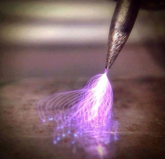
Nice pic Larry!:grin:

That's an excellent example of why a blunt tip (meaning removed point on ground end of "W" electrode) is required so that the arc plasma doesn't dance around the joint instead of it's intended destination. Any of the instructors in here should pay attention to this image and use it for teaching also... Finally, note the pattern used to sharpen the "W".

"W" represents Wulfram, or sometimes spelled Wolfram which means Tungsten, and I believe it is the letter used in the Periodic Table of Elements.

Respectfully,
Henry
Parent - By electrode (***) Date 09-25-2014 05:04
Lovely!
1.5 kV in - 10 kV out?
I agree. That might shut down your senses. :)
Parent - By CLH1978 (**) Date 09-26-2014 19:56
Totally awesome!!!
Parent - - By Plasma56 (**) Date 09-28-2014 02:57 Edited 09-28-2014 05:54
Very cool picture indeed.
Thank you for posting it.  I think that picture as great a picture as it is, shows a flaw in practice however. Maybe that was the point?

But I see it differently. I see a Tungsten ground with less care and proof of it. Nothing wrong with it, common practice, but the spiral grooves, I'm not liking that.
I don't see a blunting of a tip point either? It's just not clear to me that it has been done?

That's the rumble. Marbles rolling down grooves.

But it's only a picture right?

EDIT- I'm not sure if my camera will capture with a fast enough shutter speed. If it does, well I look forward to sharing. But the battery was dead, and the evening getting late. Tomorrow however if time allows, I'll be back.
Parent - - By ssbn727 (*****) Date 09-28-2014 06:50 Edited 09-28-2014 06:53
O)h yeah? Well then explain to us why there are so many obvious grind marks on the surface area outside of the tip on some of those electrodes? Those grind marks can attract all sorts of potential contamination that could diminish the performance of those electrodes...

Lawrence's image was intentional to illustrate and prove what happens to the arc plasma as it's transferred onto the metal shown when the tungsten electrode tip is improperly ground and shaped - period.

Respectfully,
Henry
Parent - - By Plasma56 (**) Date 09-28-2014 07:58
Grind marks- I was in a hurry. I slipped against the edge of the stone. More than once actually : )

I agree they offer up just the point you mention and what Lawrence's image represented.  Lawrence's image may have been intentional but I didn't see that clearly mentioned to that point of discussion and I replied it's what I perceived it to be, as well a quality image.

So Henry, answer three questions.
1) Was the swirl pattern the result of those grind marks in Lawrence's image?
2) Would the taper given to the electrode tip effect the pattern shape?
3) Do you still think the ground electrode tip has been blunted?

You know Henry, I think If I upset Lawrence he'd let me know. I'm hoping he has greater resources at his disposal and goes the extra mile. I have limited resources. But I'm willing to put up to further labor a point in the name of education and understanding. While I did take a few images before my camera went dead in service, my shutter speed will probably offer limited clarity to the quality of detailed image Lawrence presented. But I'm willing to give it a try.  But if your focus is on the grind marks not the angle of grind, then what's the point?
Parent - By ssbn727 (*****) Date 09-28-2014 21:35 Edited 09-28-2014 21:43
Everything is possible... However, electrode makes sense because where's this anger coming from?

I could easily speculate like you did regarding the photo but I'm not going to be baited into a "tit for tat" exchange... Feel free to enlighten us if you wish...

Finally, the questions you pose would be difficult to answer intelligently and with solid empirical evidence to support my observation without the luxury of a video filming the entire sequence as well as having the capability to study each frame of the film itself...  The photo Lawrence posted is just a snapshot of a series of events that led up to the ignition of HF transfer prior to as well as after the image was taken, hence the reason I'll defer instead...  but I will say this... If the electrode was properly shaped, the HF would not have danced around as much - if at all... I will answer the the last one with these 2 words: Definitely Not... Tapered to a sharp point, but Not blunted...

Now don't let that stop you from expressing your own opinions regarding the questions you pose... You're the person that expressed your opinion about the initial image first...

As we put it to anyone who did what you did... Where I come from we tell them: " If you question somebody's sh!+, and your sh!+ isn't tight then you're just as much a target for scrutiny as the other person, so man up and take it with a grain of salt, or W if that suits you better..." If you don't get my point, there's no reason to continue this conversation... But feel free to enlighten us with your observation and description of what actually happened for that photo to be captured and we'll all know how well you describe what only Lawrence could have actually witnessed. Got for it! Man does this thread have some worn out soles.:eek::roll::wink::cool:

Respectfully,
Henry
Parent - - By Lawrence (*****) Date 09-29-2014 12:55 Edited 09-29-2014 13:03
The pic I posted was posted because it looked cool and I made a joke with it... Nothing more...  Was making no point at all and I don't even remember where I stole that pic from... Someplace on the internets  :)

The image I posted was in my opinion "obviously" a HF arc on a workpiece that did not have a work lead connection... so the HF plasma danced around prettily for a picture (while searching to complete a circuit for the welding current)..  Could have been on a fingernail for all that it matters.

All this blather about spirals and straight lines... About blunted points vs non blunted points must be put in a frame of reference in my opinion.

General "MANUAL" steel or stainless GTAW of thicknesses greater than .063 and any decent power supply made in the last 25 years will produce good/great arc starts with HF and a pointed electrode.  Most newer machines are pushing between 70-85 open circuit volts and any HF that crosses the gap will pull the current down and make a solid arc start.   As long as the prep provides longitudinal striations the arc is going to jump just fine; whether absolutely straight or spiraled.  

The only time a difference in included angle and spiral vs straight striations, is going to be pronounced in application/bead profile is going to be on very thin gage metal or automated GTAW where AVC (adaptive voltage feedback) controls Z-axis (arc length)  In these cases the taper and end prep can be pretty important if consistency is what you are after.
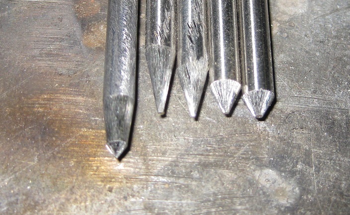
If you look at a needle sharp tip prep under magnification it will look rough... Arc strikes tend to transfer those rough bits of tungsten across the arc and into the puddle, which can be trouble for RT... This is magnified as the starting arc current is increased....   For example that needle sharp point may make a much softer arc start on a 10 amp weld with a 1/16 or .040 tungsten electrode... But that same tip prep on a 90 amp start might blow some of the rough tip away into the puddle.

Moral of the story...  The practices outlined by manufacturers for tip prep are true; however, the dogmatic rejection of small imperfections in tip prep for most manual GTAW is going a bit overboard in my opinion.  

I think the larger issue for most manual GTAW is threefold.
1. Continuing to use a tungsten electrode that has been contaminated (laziness)
2. Overheating electrodes or using the wrong sized electrode... One size does not fit all.
3. Poor arc starts related to low current for large electrode diameter... One size does not fit all.
Up Topic Welding Industry / Technical Discussions / Vertex angel (GTAW) less or more give good penetration
1 2 Previous Next  

Powered by mwForum 2.29.2 © 1999-2013 Markus Wichitill