if the weld is sound, i.e., no reflectors, the angle of the transducer is immaterial
The angle is imperative not immaterial. Picture a knife edge. Turn that picture in your mind (or if you have a pocket knife in reality) until your looking at the flat of the blade. Which angle gives you more surface to reflect from? If I impinge on a planar at 45 degrees, and that so happens to be parallel with how the planar is oriented, I am hitting the blades edge. the wave front is going to skip over and below it. If your looking for a lack of fusion, inherently, that angle of the lack of fusion at the WM/BM boundary inherently has a direct impact on detectability. if it's 45 or so from the perpendicular, it can cause a significant loss of sound through redirection/refraction/reflection etc. for straight up straight down D1.1 UT, It's simply Distance gain size. (DGS) Amplitude of response is part of the A-B-C = D formula. If it's +4 or +12 or -4db it's all in db, not is it a crack, is it LOF, or whatever it may be.
but once a reflector is found, don't you "peak" the response by using the transducer that produces the maximum response so you can better characterize
Flaw characterization never comes into the picture. Where understanding echo dynamics comes into the picture is in determining if something is going wrong, where your sound is at, and a host of other matters. Table 6.7 precludes the use of different tranducers, though many procedures do so anyway. If I have a 3" piece, I'd be using 45/70/70 ducers for instances rather than 70/70/70 as you would with 5/16".
So what does the technician do when they hit a free edge bounce in a backing bar that returns? reject because the signal shows up as in the second leg, does he or she recal, change angles, hunt and peek for some phatom indication that doesn't exist? Or do they note the phase change/subsequent conversion of the wave front 180 from propagation and possible constructive or destructive interference that is a clear sign of a free edge rather than a flaw? (that by the way is why I won't buy a scope not capable of RF waveform display. A scan rectified is nice and all that, but there are times when it can hose you)
I for one can think of many structural UT techs that bit the bullet on that one. Including myself 19 years ago when I first tried my hand at D1.1 UT.
Then there is the WM/BM boundary. Every material has a boundary unless they are contiguous/homogenous. It's not unusual to get a minor return out of phase from the HAZ area and or BM/WM interface. Those in particular have to be watched closely as they may or may not be haz cracking (whose angular orientation may or may not be suited for the angle of impingment).
All in all, the only thing the bevel angle does for you is give a starting point.
Regards,
Gerald
I understand what you are saying, but my point was, if there are no reflectors, i.e., no defects present, the bar is homogeneous, the angle is immaterial. The sound will not return to the transducer if it is attenuated by the bar if it is long enough (or your range is set short enough).
I also said that the reflector is accepted/rejected based on it's rating per D1.1. The characterization is something above and beyond what D1.1 requires, but the client often requests, i.e., is the defect porosity, a crack, etc. How deep is the top edge, how deep is the bottom edge, how long, etc. is always of interest if a repair is required. The welder wants to know what he is looking for before starting to excavate the weld.
I will look into the phase conversion from backing bars that you mention. I haven't tried to use the full unrectified wave when using UT for weld inspections. I'll give it a try.
Thanks for the explanation.
Best regards - Al
My point was, you cannot state "no defects present" without taking those factors mentioned into account.
Regards,
Gerald
I may need to make my question more clear. The areas that were not rejectable are for example:
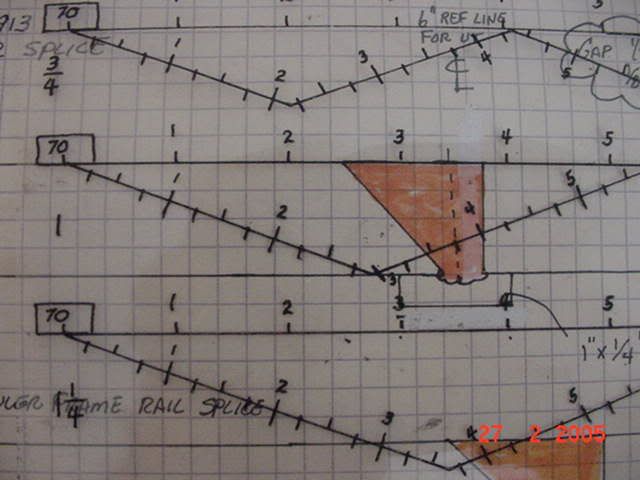
Scanning a T joint 3" thick
-This is a #5
-I would have to use a 45 for the top quarter and a 70 for middle half and bottome quarter.
But my question is that if I see something in the middle half with a 45 and I determine it rejectable by size, not location is it still rejectable or do you leave it according to tables 6.2, 6.3, and 6.7.
This also goes for areas in HAZ doe they stay?
I would have to say I will follow the code but make sure to include the know indications in the UT inspection reports.
Boy, this sure got complicated, echodynamics, RF,
You gave quite a thickness range in your O.P., 3" Tee joint makes it easier. So,
Since F or XF applies, and you say the indication is near the middle, and assuming from the thickness it is a double bevel groove, (TC-U5), you may be looking at the fusion face on the opposite bevel, in which case, yes, you should reject it, because technically you have just applied F. If you can get to face C, you could verify the location of it freom there, with a 45 deg shoe.
Remember, F isn't an option when it's called out, it says "shall be further evaluated...."
As far as AWS UT techs not knowing how to characterize indications, or recognize backing bars, or use a DAC, I refer you to Commentary C-6, and Annex S.
I still don't think that you understand the question.
Yes I should have explained a little better but there are many different thicknesses and majority of our CJP are BTC-U4.
Yes I can further evaluate it with another angle or from face C but if I am using a 45 for the top quarter and I see something outside of the top quarter is it rejectable. Sure I can evaluate it with a 60 or 70 and maye even from face C but I still find a true large enough reflector to reject, but it is outside the top quarter, is it still rejectable according to D1.1?
C-6 and Annex S are very informative.
OK, I got ya, here's the rule that I apply with my inspectors. Now keep in mind that whether or not Note F or X-F applies will depend on the thickness.
Here goes. If you are looking at the top quarter with the 45 then ONLY LOOK AT THE TOP QUARTER. I'm not yelling at you, btw.
Now, if note F applies, you will be looking at fusion faces with the appropriate angle anyways, AFTER you've done the 45 70 70 inspection. Now Note F applies for any thickness greater than 1 1/2" butt or Tee weld, period.
Now let me say something without you taking it the wrong way. In your original question, you stated that you are doing a Tee weld which requires a #5 inspection. OK, Look at table 6.7, the only thickness range in a Tee weld that requires a #5 procedure is 2 1/2" to 3 1/2", and also this requires F or XF. That is why I focused my answer on this specific thickness range.
Your question is easy enough to understand, take some time to understand table 6.7, note F, and X.
Note F and XF apply to thickness and weld type.
Thank you. I was not trying to make my question so difficult to understand.
This is the answer I was looking for.
Annex S is informative, C is commentary, neither binding unless called for by procedure/contract.
Recognizing backing bars is knowing where your sound is and what it's doing.
As for the commentary:
para 6.27.6 paraphrased; indications in root and fusion face shall be further evaluated with either 70 60 or 45 whichever is nearest to being perpendicular to the expected fusion face. I fail to see where it states evaluation by anything other than a different angle.
The resolution comment in the commentary section under C 6.26.12 is insufficient to say the least and more apt to confuse than help.
If and when "informative" annex S is invoked, AWS still leaves the tech hanging out to dry. Figures S9 through S12 Just don't cut it.
A Level 1 should be able to figure as much out as annex S shows. Especially S9 and S10. I've yet to see the perfectly sperical porosity or slag inclusion, much less the signals portrayed in the figures unless I am on the IIW block. More often than not there is some combination of all.
Therefore, there is nothing "complicated" about it, it should be the norm not the exception.
Regards,
Gerald

 Nice tip about using the "block" in Autocad, Al.....I'll have to give that a try.
 Forum
Forum


