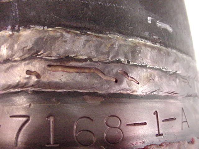
Recently we had a representative come to our shop to inspect a job. Upon inspection there were 4-5 areas noted that had weld surface defects. We would call these defects worm tracks or wagon tracks, and were surface defects only on non CJP joints. There were no pinholes or porosity associated with any of the defects. Subsequently, we repaired the defects by die grinding and blending to remove the defect only with no significant impact on the weld size (checked and verified by inspector). The inspector insisted that the defects were not in conformance with AWS D1.1, but the code does not address this type of situation directly so I didn't have any ground to stand on to state that they were within code. So my question is: In this type of situation what are these defects considered in D1.1, and are there allowable limits to the defect width, length, and depth as there are with porosity, undercut, concavity/convexity, etc.?
After some research, I have determined the most likely causes for the defects were either too high of voltage, not a long enough wire stick-out, or the welder moved too quickly through these areas. These welds were made with an FCAW E71T-1 electrode, .045" diam., with 100% CO2 shielding. I would not consider this a 'problem' per say, but something that I should watch for when inspecting welds, so I would like to know what is and is not allowed regarding the defect size. I know porosity limits for statically loaded non-tubular connections are not more than 3/8" in 1", and not more than 3/4" total in 1' - however, I would not consider these defects to be porosity as they were surface only.
Any help here would be greatly appreciated. Thanks in advance!
Take a look at D1.1(2006) 5.4.6 and 5.26 (5.26.1.3 specifically)
Jason
5.26.1.3 - Incomplete Fusion, Excessive Weld Porosity, or Slag Inclusions
Unacceptable portions shall be removed (see 5.26) and rewelded.
As I stated, the unacceptable portions were removed by grinding, and there was no need to deposit more weld metal because there was no deficiency in weld size after the grinding. These defects were very shallow, and the welds were checked and verified to be acceptable. If I didn't know where these spots were I wouldn't even be able to find them.
Perhaps I didn't state the problem clearly. The problem was not with the repair, but with the defect. I do not see anything in D1.1 that addresses this type of situation for inspection and criteria for acceptable and rejectable defect sizes. Maybe it falls under a category I am not considering it to be a part of - like porosity, but I would not consider it porosity. Would you if you were inspecting these welds?
Thanks for the reply, let me know what you think.
drewp29,
There is always difficulty when defects are noted in nonstandard terms. "worm tracks" are typically surface porosity. This is when the slag solidifies prior to allowing the gases to escape. What you have is a cavity where the gas was trapped. This is very common with E71T-1 when your voltage and/or torch angle is off. "Wagon tracks" are slag lines that are on top of your root pass. This is most commonly only found when performing RT of a CJP, rarely when performing UT. This can not be seen by looking at the final pass of a CJP. AWS D1.1 table 6.1 has limitations listed for many defects and would be a good place to start. It sounds like you are dealing with surface porosity.
Thanks - and I agree that these 'worm tracks' (I shouldn't have called them wagon tracks) were formed when the slag solidified on the weld surface and the gas was not allowed to escape.
I guess I have always considered porosity to be defects which penetrate the weld much more so than these did - like pinholes. And I have seen pinholes that I would consider 'worm holes', that is, the worm tracking starts with a pinhole.
So if this really falls under the category of porosity in table 6.1 then the guidelines for acceptance/rejection would be as I stated above?
Thank you for the help.
I know what you mean when you say that the "worm tracks" aren't specifiaclly under any particular defect category. It's difficult to call it porosity when there are no holes, it isn't lack of fusion, undercut, or any of the usual terms. "Wagon tracks" and "worm tracking" are used because the terms describe what it looks like.
I evaluate "worm tracks" as sort of a combination of overlap and convexity; as if there are 2 separate beads that don't quite blend together. Basically, sharp changes in profile are not desireable so I have them ground to blend them out and then make sure there is adequate weld throat. Then of course I may see some classic porosity exposed by the grinding. Seo at that point - grind deeper.
If I don't see porosity exposed, and the throat is OK, I move along.
If the tracks are minimal, shallow, and rounded I might let it go (might/ might not). What I look for is that the countour is no worse than you'd get from SMAW ripples, or how 2 beads should tie together
Naturally, the "wagon tracks" are a clue that something is on the verge of becoming a bigger problem, so I check the gas regulator. It OK then I watch to see if the gun is being held at too low an angle - so that the venturi effect pulls air into the gas shielding.
When it comes to porosity per D1.1, only piping porosity is addressed by the visual acceptance criteria of Table 6.1. The discontinuity described is not piping porosity as I understand it, thus it is not addressed by D1.1 and it is not rejectable based on D1.1 criteria.
It is caused by a gas bubble (carbon monoxide) getting trapped under the solidified slag and pushed by the liquid/solid interface as the weld puddle progresses as defined by the welder's travel speed.
Reducing the wire feed speed and travel speed can reduce the tendency to produce the elongated porosity since more time is allowed for the gas to evolve and dissipate.
Best regards - Al
Thanks again for your help~
The defects in question were definitely no worse than weld profile produced by SMAW. The thing is, like I said, there were only about 5 places over a very large amount of welds that had this condition, and the defects did not have sharp transitions. When I visually inspect our welds I try to look for the normal discontinuities - piping porosity, undercut, excessive/lack of reinforcement, surface inclusions, lack of fusion, arc strikes on based metal, spatter, etc. But the smaller defects such as these will often go unnoticed until blasting occurs and the defects are more visible. We try to train our employees to spot defects during welding and blasting/painting, but still some things go unnoticed. I guess the lesson here is no company's welds are perfect, but the customer is always right, so if they see something they don't like and you can't negate it by code requirements then you bite the bullet and make the repairs.
Is this similar to the surface condition you guys are talking about?
~thirdeye~
That's what I was talking about.
Best regards - Al
I hope that guy is no longer welding.
3.2
Since the long worm track has a piping porosity tube at the end, I count the entire length as the diameter of a piping porosity hole.
Gentlemen,since this is the first time i have seen something like this, can anyone tellme what the root cause may be?/
Hello lonewolf658, there are really a number of possible contributors to what you see in that picture. Those welds were done with gas-shielded FCAW wire. Sometimes, if this wire is left out too long in an environment where the humidity is relatively high or it rains a lot(humidity, moisture again) this can be picked-up by the fluxes inside of the wire. When the welding is done, this moisture(dissassociated hydrogen) can be introduced into the weld puddle and cause the types of issues that the picture shows, the gases don't escape before the weld metal solidifies. Use of certain types of nozzle anti-spatter gels in an excessive amount can also cause similar types of problems. Improper cleaning of sawing or metal-working fluids can sometimes cause these types of issues. Failure to properly remove external/internal pipe anti-rust preservatives(shellac and other items), could possibly contribute or cause these types of issues as well. Excessively high voltage and low wirespeed can sometimes exhibit something like this in welds. Even rust could possibly cause this sort of item to show up in a weld in some cases. I am sure others could point out additional types of contributing factors or elaborate in more detail about the ones that I have mentioned. These are just some that come to mind. My $.02 for the evening. Best regards, Allan
Thx Allen,i'll take the 2 cents from any of you guys ,i got nothing tolose and your 2 cents is money in my future .
Hi,the first we will grinding the welding .
Have you tried to fuse over the worm tracks with a tig welder if you try this sometimes it will blend in and if it's a bad weld it will blow out all over you. Just some to try.
M.G.

 Forum
Forum


