Theoretically your numbers are correct. I don't have D1.1 with me at the moment, but look through D1.1 for a z-loss factor. Depending on the process, root opening, plate or tubing, the weld size may have to be bigger. Without looking in my book, I'm not sure a 45 deg dihedral angle will have a z-loss or not. The values that your GAL calculator give you are based on theoretical intersecting planes, and assums you're getting weld penetration all the way down into the root.

 By 803056
  Date
Date 11-09-2010 14:47
Edited 11-09-2010 14:54
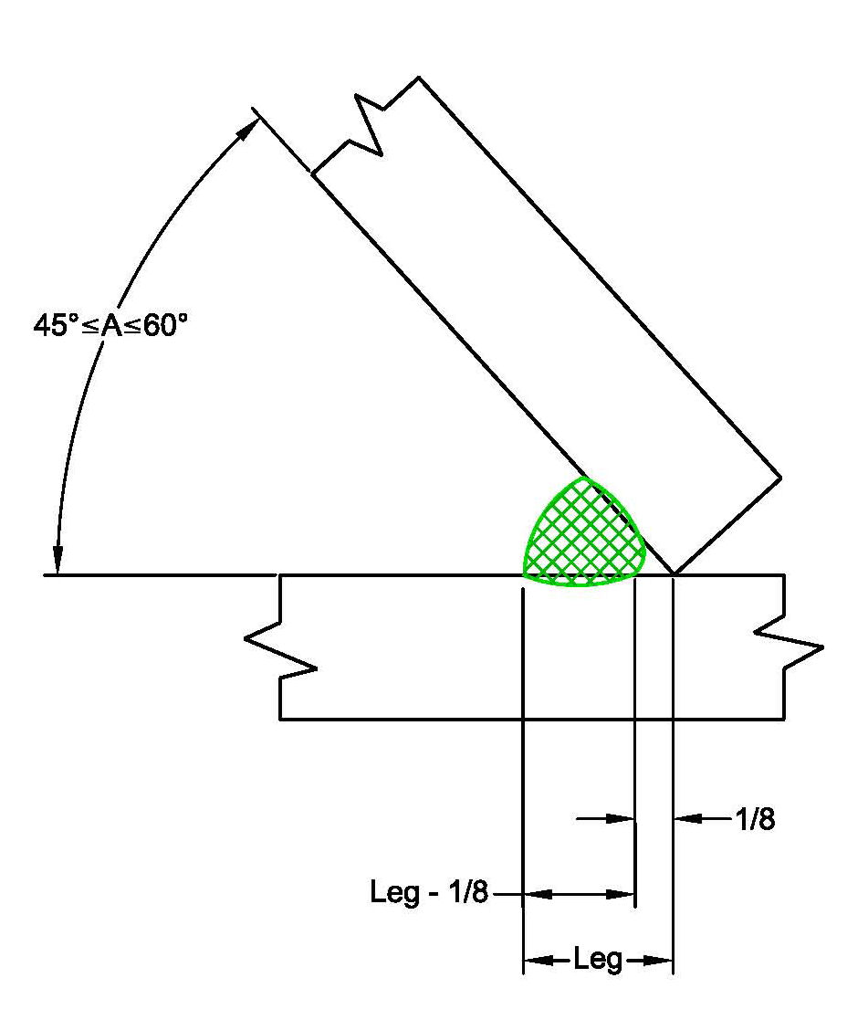
Hand it back to the engineer or the fabricator to determine the required weld size. The design engineer is suppose to provide the minimum throat required and the fabricator is suppose to provide the leg dimensions required to provide the necessary throat dimension. However, the fabricator also has to take into consideration the welding process, welding position, and the dihedral angle to determine the Z-loss factor which has to be considered when determining the required leg size.
A simple fillet weld symbol cannot provide all the required details. A sketch depicting the joint details is the most expedient means of conveying the information to the EOR, welder, and the inspector. By the way, don't forget to look for the EOR's approval stamp on the drawings.
The imbedded sketch is an examples that depicts a welded skewed joint with the Z-loss taken into consideration. The Z-loss is not a fixed value, but is dependent on the welding process, welding position, and dihedral angle.
The CWI should verify each party has considered the requirements of D1.1, but shouldn't be determining the necessary leg dimensions on the shop floor. That is the fabricator's responsibility and the information should be provided on the shop detailed drawings. The EOR is rsponsible to verify the fabricator calculated the numbers correctly before approving the shop drawings.
Best regards - Al


