Not logged inAmerican Welding Society Forum
Forum AWS Website Help Search Login
Up Topic American Welding Society Services / Technical Standards & Publications / Is this FP Weld Symbol
- - By Nalla (***) Date 02-17-2011 21:52
Dear Experts
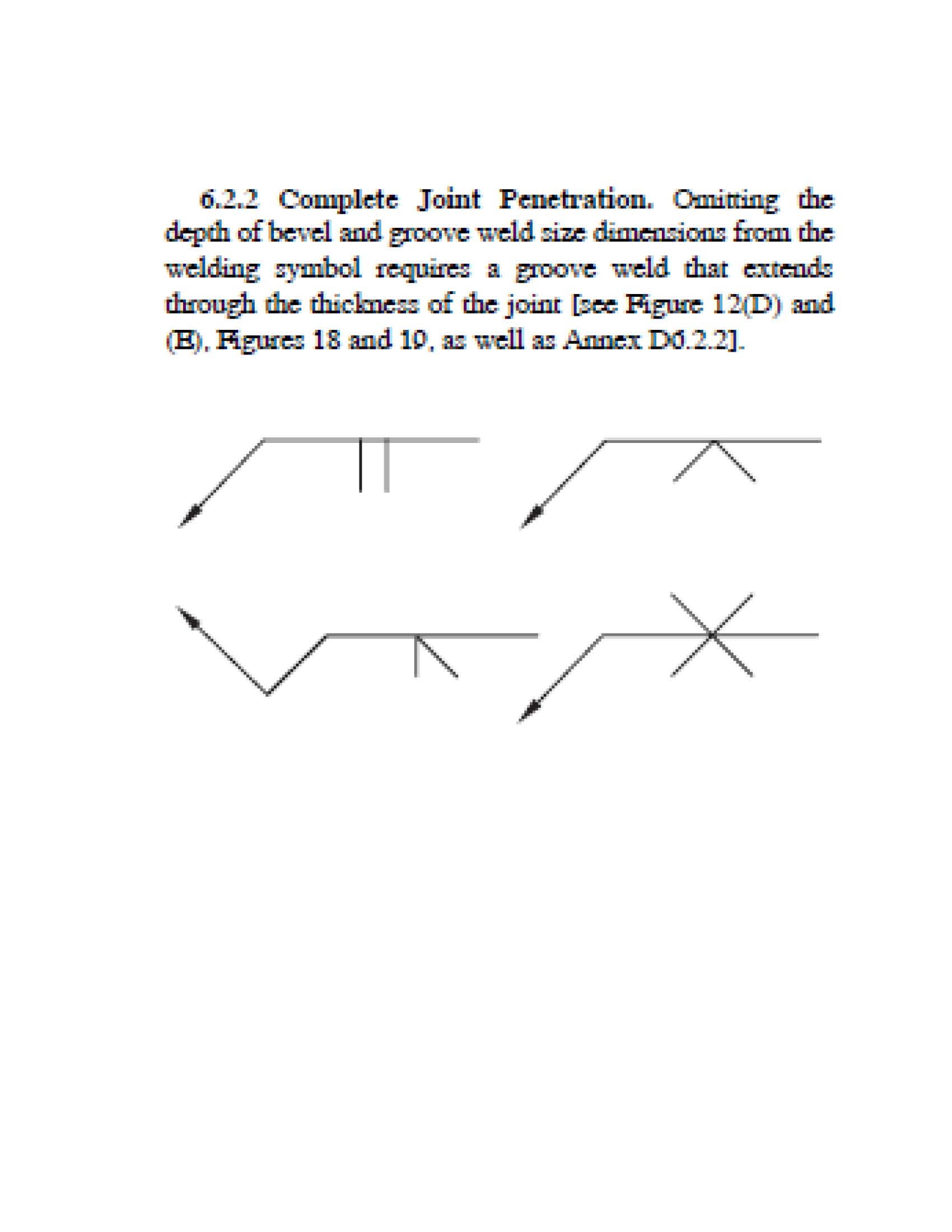
Pls revuew attached abd advise if it is FP Weld Symbol.
If yes whay it must be?
Thanks
Attachment: ISTHISFPWELDSYMBOL.pdf (112k)
Parent - By welderbrent (*****) Date 02-17-2011 23:15 Edited 02-17-2011 23:35
If by 'FP' you are asking if it designates a 'CJP' (complete joint penetration), then no.  Not with the information provided.  It would be very possible to make it so, but it is not as shown.  It calls out a fillet weld from one side and a PJP (partial joint penetration) weld from the other because of the angle of the plate along with any bevel needed to get to the 45* shown. 

In A2.4 Standard Symbols for Welding...  section 6.13 and 7.7 with Figure 31 shows the requirements for welding symbols for skewed joints.  Figure 31 shows a Complete Joint Penetration weld.  From what I saw of yours, it did not.  6.13 says "When the angle between the fusion faces is such that the identification of the weld type and, hence, proper weld symbol is in question, the detail of the desired joint and weld configuration shall be shown on the drawing with all necessary dimensions (see Figure 31)."  The drawing you attached doesn't show all the dimensions that would indicate it to require a CJP weld.  IMHO. 

Also, much of the time, the engineer will call out CJP welds in the tail of the reference line on the welding symbol as is done just to the right of the symbol in question.  Since they used the tail to make that clarification for one weld I would tend to think they should be consistent and use it elsewhere if they wanted CJP.

Have a Great Day,  Brent
Parent - By Duke (***) Date 02-18-2011 01:02
I think it is a full pen... groove weld symbol with no size? Full pen
Parent - By Lawrence (*****) Date 02-18-2011 02:39
I think Duke said it.

The groove weld with 45 degree single bevel (all around... um something) shows either a back weld or a backing weld.  I don't think the drawing makes it clear which it is.
Parent - - By ctacker (****) Date 02-18-2011 02:42
I would agree with Duke, I see no weld size specifying partial joint penetration. and when weld size is not shown, it shall be considered Complete penetration!
Parent - By TimGary (****) Date 02-18-2011 12:01
Agreed. It's FP.
Parent - - By waccobird (****) Date 02-18-2011 10:02
Nalla
By the information shown and no further direction from the E.O.R. 3/4's of the replies are correct.
As Duke said according to AWS D2.4 if no indication of weld size, or notes in the tail it is indicated CJP Complete Joint Penetration.
That is some of what you have project and production reviews, to accumulate (RFI) Request for information to ask the E.O.R to clarify.
Good Luck
Marshall
Parent - By welderbrent (*****) Date 02-18-2011 14:52
Gentlemen, 

Overall I agree as well.  I would direct any who would be so inclined to review this thread:  http://www.aws.org/cgi-bin/mwf/topic_show.pl?pid=193959;hl=D1.1%202.2.5.3  .  I still believe that stand completely. 

Now, having said that, my first post is not to reflect that it would not in practice be a CJP.  But to what extent does it MANDATE CJP?  Will it have to be UT'd to prove 100% CJP?

The lack of size and CJP being incorporated into the welding symbol apply to groove joints, but how about in SKEWED JOINTS?  Please note D1.1, Clause 2, 2.2.5.2 'Fillet Welds and Welds in Skewed Joints'.  As well as my previously mentioned A2.4, 6.13 & 7.7 with Figure 31.  All state the REQUIREMENT that a detailed drwg be included which would show all necessary dimensions.  Slightly different than the CJP being presumed in joints of standard configuration.  Specifically the Z loss factor is to be accounted for. 

2.2.5.2 paragraph (2) "For welds between parts with surfaces meeting at an angle less than 80* or greater than 100*, the shop drawings shall show the detailed arrangement of welds and required leg size to account for effects of joint geometry and, where appropriate, the Z-loss reduction for the process to be used and the angle,"

A2.4, 6.13 "Skewed Joints. When the angle between the fusion faces is such that the identification of the weld type and, hence, proper weld symbol is in question, the detail of the desired joint and weld configuration shall be shown on the drawing with all necessary dimensions (see Figure 31)."

Now, one oversight then on my part would have been to stress the need to have already used the RFI system to clarify the symbol and it's desired result.  It should not be left to the Contractor/fabricator nor to the inspector to guess the intent of the engineer. 

But, on the face of it, I don't see how it could be concluded that the symbol in question MANDATES CJP, until the engineer speaks out, since it is missing critical components according to A2.4 & D1.1, 2.2.5.2.   There is a detail of the joint but it lacks the REQUIRED dimensions. 

Again though, in practice, with that angle it may well be a CJP when the weld is completed.  But if it is MANDATED then one needs to take care to make sure the two welds meet.  The Z-loss area can mess up many welders if they don't do proper backgouge/grinding. 

Just my two tin pennies worth.  Please don't count me, necessarily, as being the 1/4 of the replies that are WRONG.  There is more here to my estimation than just the CJP because there are no dimensions.  I am not afraid to take a differing stand here as long as we don't start a feud over it.  Like I said, overall I agree with the CJP requirements on welding symbols lacking dimensions.  But, Nalla needs to go to the engineer.  That is always the best course, especially if there is disagreement between the interpretation of the Fabricator and the inspector. 

Have a Great Day,  Brent
Parent - - By jwright650 (*****) Date 02-18-2011 15:53
"Pls revuew attached abd advise if it is FP Weld Symbol.
If yes whay it must be?" -quote

Yes, the symbol shown in the sketch is indeed a cjp(full penetration) on the arrow side, with a 1/4" fillet on the other side.

Welder must fill the groove on the arrow side, backgouge to sound metal on the other side, fill to flush and then add a 1/4" re-inforcing fillet.
I don't see any confusion in this weld symbol, unless this is not what the engineer had in mind.
Parent - - By Lawrence (*****) Date 02-18-2011 16:57
John,

Just for the sake of fun conversation.  And the extension of an enjoyable thread.

Are you absolutly sure the "Welder must fill the groove on the arrow side, backgouge to sound metal on the other side" ??

I see nothing in the drawing to distinguish sequence of operations for a back weld or a backing weld.

It's not one of those things your supposed to assume is it?    Just seems like an important piece of information that would be better included on the drawing.

Whadda ya think?
Parent - - By jwright650 (*****) Date 02-18-2011 19:21
Ok, ...hmm, just thinking outloud here....why would the welder sequence his welding in any other manner? Would he want to place the backing weld first, then back gouge into the open groove and fill then fight the distortion and trying to straighten his plate back to the designed skew? or would he weld out as I described in the earlier post and have more of a balanced heat across his joint so the plate would move less?

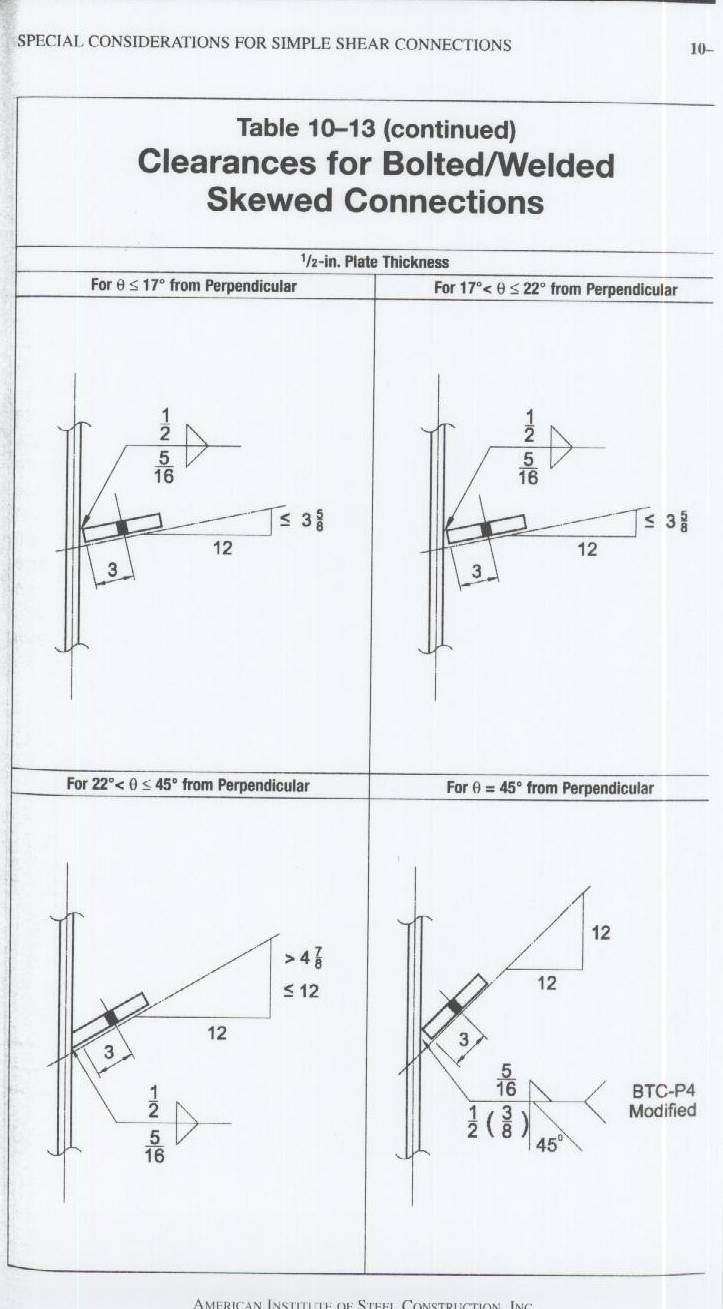
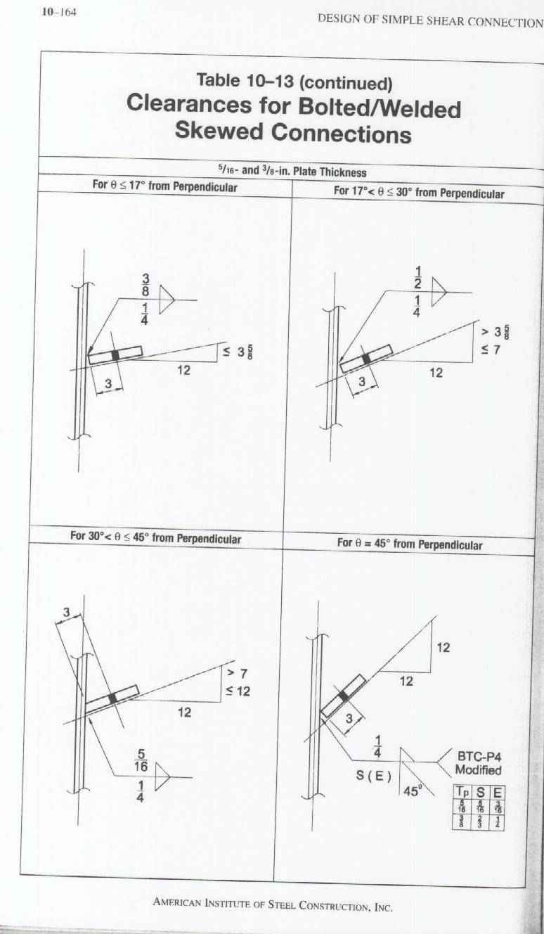
I see that same symbol on a pretty regular basis and I spelled out the sequencing typical of what I see regularly. If the designer meant to have a modified partial pen BTC-P4(like in Table 10-13 of the 13th edition of the AISC's Manual of Steel Construction), then he should have indicated the depth of bevel and the effective throat in his welding symbol.
Parent - - By welderbrent (*****) Date 02-18-2011 21:10
John,

Not trying to be a pain or funny, notice the wording you used: "Would he want to place the backing weld first,". 

The "backing weld" is always placed first.

A2.4 (not preaching to you, teaching for those who may not know or need reminding) subsection 6.7 Back and Backing Welds: 6.7.1 General. The back and backing weld symbols are identical.  The sequence of welding determines which designation applies.  The back weld is made after the groove weld, and the backing weld is made before the groove weld (see 6.7.2 and 6.7.3).

A3.0 Standard Welding Terms.  Backing Weld: Backing in the form of a weld.

Watch that terminology.  LOL!!  We knew what you meant.  I think.

In this case, since the detail doesn't designate rather it is a back or backing weld, the order is left to the discretion of the fabricator. 

Your chosen order would distort the members less because of the direction of 'pull' stresses and little weld reinforcement on the bevel weld side.  Then weld from the opposite side which would tend to pull because it is built up past the line of the part.

I would agree with John's chosen sequence though it is not mandated by the detail.

Have a Great Day,  Brent
Parent - By jwright650 (*****) Date 02-18-2011 21:27
excellent reading Brent...terminology lost in translation...LOL

Have a good weekend folks.
Parent - - By welderbrent (*****) Date 02-18-2011 16:41
Nalla,

I'm going to back totally away from my reservations about this symbol.  The other posters are men I respect entirely too much to even begin to take a contrary stand to their interpretation.   And, I too believe wholeheartedly that when the dimensions are left off of the welding symbol that it represents a CJP. 

I simply saw what I thought was possible miscommunication from the engineer based upon the aforementioned clauses on skewed joints.  But since I have been totally overruled I will concede.  This is not negative toward these men.  I trust them to have given both of us accurate advice and direction on your question.

Have a Great Day,  Brent
Parent - - By Lawrence (*****) Date 02-18-2011 16:51
Hey Brent  !

This is still just an internet chat forum.

*Nobody*  should be making engineering level constructional decision based simply on the postings here.  Even with the formidable company we keep :)
Parent - By 803056 (*****) Date 02-18-2011 17:30
Since I freely admit I'm an idiot, I usually refer to the applicable standard to see what it has to say about a question before I toss my hat into the ring. The attached file is what A2.4 has to say on the subject.
Based on A2.4, I would offer that it is a CJP with a fillet weld on the side opposite the groove weld.

That isn't to say the joint detail is prequalified per D1.1 or that it is a good joint detail, simply it is my understanding of the meaning of the welding symbol as drawn.

Best regards - Al
Parent - - By welderbrent (*****) Date 02-18-2011 17:57
I understand that Lawrence.  Thus my suggestion to RFI the engineer.

I just don't want to go overboard trying to make a point that appears to not be relevant.  No need for that kind of disagreement or at least percieved disagreement.  I felt it was starting to look like I was going to stand on my position regardless of the comments of others.  I TRY not to get too defensive of my beliefs.  I am way too new at this yet.  There are items I take a pretty hard stand on.  And, I too feel that the Code is pretty plain on most items.  But, as we often see, plain to one is not always the same plain to another.

Al,  I understand that section, as much as my limited mind is able to.  As I hope indicated in the link to a previous thread on a similar discussion.

I just thought the engineer slightly remiss in the detail as per the clauses I already sited taking into account the skewed joint and that there may be room at that point for the symbol to not be MANDATING a CJP.

I'm not trying to put anyone in the place of God as all knowing, all wise, with the only correct answer.  But the overwhelming opinion seemed to be that my question was not relevant.  And by men I truly respect very much.

No offense taken on my end and I hope none taken by others.  Such was not my intention.  Nor to make it seem like I was doing obeisance to an elect authority who could not be challenged.

If looked at for the value of getting an accurate answer from the engineer, I think my question of the symbol still has some merit.  But,  I am not going to defend it as being the only right interpretation.  Only a question that to me appeared worth asking. 

My bowing out should not be construed as feeling like I was beaten into submission.  I did so to help end any confusion my question may cause.

Thanks for your edification Lawrence.  All you guys that have posted here thus far are on my 'desired counsellors' list.  I respect your opinions.  If I strongly disagree with anything that many here might post I would go the 'Official Interpretations' route to see what those in more official authorithy thought. 

Babbling.  Thanks.

Have a Great Day,  Brent
Parent - - By Duke (***) Date 02-19-2011 03:54
WTF if folks don't have different views and then go ahead and discuss them, we'll never learn anything
Parent - - By welderbrent (*****) Date 02-19-2011 21:30
Duke,

That was my intent in a way,  I felt I learned something and that I was going a wrong direction.  I hope all, as I beleive I have, including the OP have picked up some information from this thread.  So, I wanted to tell Nalla I thought it was time to ignore the direction I was going and take the advice of you other advisors.

Honest, I learn alot from some of the 'banter' and 'challenges' we all experience from time to time.  But there is usually a time to back off and say, 'OKAY, maybe I misunderstood or at least wasn't thinking right.' 

It does take discussion, breaking out the books and doing some study and getting well rounded advice, counsel, criticism, exhortation from others.  We will always have different views or this would really be a boring world with absolutely no way to expand knowledge.  But at the same time, there are often proper times to back down and say, 'I concede. My direction was wrong.' 

Passion can be a key element to defending our position.  And if not careful it can get out of hand.  We start saying things that don't need to be said.  And, some times we need to just stop the conversation and be able to agree to disagree.  Part friends.  And see if time doesn't lead one or the other to learn/experience new information that changes their mind.  That is learning.  Not continuing to carry on a debate for the sake of not backing down.  Pride causes many a friendship to be broken for no GOOD reason. 

Please don't take my backing off wrong.  Nor anything else I said in the past couple of posts.  I think there was much good info here related to the OP query. 

Thank you for your time and contributions here. 

Have a Great Day,  Brent
Parent - - By 803056 (*****) Date 02-20-2011 15:45
When in doubt, make the Engineer earn his keep. There is nothing wrong with an RFI if it appears the welding symbol (or any detail) is open to misinterpretation.

The number of welding symbol errors on drawings is scary. I would estimate 85% of the drawings I review have welding symbols errors on them. Some are simple, some are borderline gross incompetence. 

It is amazing where engineers, designers, inspectors, and welders go to seek clarification when there is an issue about the proper interpretation or use of welding symbols. It would be difficult to recount the number of times I've seen designers "make-up" their own welding symbols when they don't find one that suits their needs. Some are comical, some downright dangerous.

My point was that the interpretation of the welding symbol should be straight forward. Don't mix workmanship with welding symbols. One has little to do with the other. Granted, AWS D1.1 has a couple of clauses that clarifies the use of a welding symbol used in conjunction with D1.1, but that is a situation that doesn't apply across the board with all other AWS welding standards. It is the designer's responsibility to use proper welding symbols if he is going to use them on a drawing. The fabricator has every right to expect the welding symbols to be correct. If the welding symbol "as-drawn" is interpreted properly in accordance with AWS 2.4 (with the edition in place when the drawing was made), the fabricator has every right to expect additional compensation if the designer insists on corrective work to compensate for what was delivered.

I was on one project where we back charged the designer for improper or incorrect welding symbols. The sum was substantial and we collected for the delays in production and delivery because of the errors the designer made. The errors were so obvious that it was questionable if he even owned a copy of AWS A2.4 or if he was simply using the symbols he saw drawn on the walls of the Men's Room.

Best regards - Al
Parent - By 99205 (***) Date 02-21-2011 00:58
RFI's are a job saver.  Learned my lesson once by not doing a RFI on some 10" Stainless flanges.  They were to be positioned 10 degrees off of normal.  Wording was very vague and since it was all new equipment I figured it was misprint.  Now if there is the slightest question I RFI.
Parent - - By welderbrent (*****) Date 02-21-2011 14:22 Edited 02-21-2011 14:24
Boy do I agree with you about the engineers and their details Al.

On THREE current jobs I am inspecting the details from the engineers have been so out of line with the Architecturals and even some of their own plans it is hard to even GUESS what they want.  Then, the detailers doing the shop drwgs have not always gotten all the right answers before finishing their work and the engineers are not looking those over good enough to ask for changes, just stamping them.

Then, I come along.  I ask, 'why don't these match the details?'  'Do you have an RFI for this change?' etc.  And get told, 'The engineer said just do it that way.'  I just shake my head and say 'Get it in writing. I can't sign off on it since it doesn't match the prints or details.  I know, none of them match, but they have to before I can approve this work.'  After a few days I get my 'reverse engineered' RFI clarification and all is good.  Usually. 

Nobody is REALLY looking at the work of others and the fabricator/erectors are just doing their own thing not realizing how critical it is to get the details worked out BEFORE they do the work. 

And if I were in Nalla's shoes, I would ask for an RFI.  Just because I wanted to end my part in the discussion doesn't mean I am clear as to interpretation of the symbol.  And as has been pointed out many times, even here by you and Lawrence, this is just a forum, what we say isn't the TRUE issue.  If it were only a simple matter of personal understanding that needed some clarification that would be one thing.  But if it were my job I would now head to the engineer through an RFI. 

Of course, it could be the easiest way is to just consider it a CJP unless that would cause a problem because it would then need continual visual inspection and UT.  One thing leads to another. 

Thanks.

Have a Great Day,  Brent
Parent - - By Lawrence (*****) Date 02-21-2011 14:53
Great point Brent!

Maybe the majority agree on the forum that it's a full pen weld...  Maybe we are even correct, according to AWS standards....  BUT THAT DOESN'T NECESSARILY MEAN IT'S THE INTENT OF THE DETAILER!!!...GREAT POINT!

That is why going up the food chain to get a clear determination is such a wise move.

What's the difference ?   

1.  Well rework if we do PJP and CJP is the truth.

2.  Way more time ($) in preparation operator difficulty to do CJP and it's all wasted of PJP was the detailers intent.

Both are loosers....   Best to be sure.

I appreciate your insight.
Parent - - By jwright650 (*****) Date 02-21-2011 15:12
L,
Let me throw in another senerio.
The designer sees the natural groove created by leaning the square cut plate over to a skew and uses the groove weld symbol even though a fillet weld would do the job(see Table 10-13 in the 13th ed. of the AISC's Manual of Steel Construction)....then it could be up to amount of skew....ie. 5/16" and 3/8" plates skewed 0-17° from perpendicular can be fillet welded(again, provided the full plate thickness isn't required in the calcs) with 1/4" fillet on the closed side and 3/8" fillet on the open side of the joint....and if the plate is 1/2" the fillet weld for the same skew would be 5/16" fillet on the closed side and 1/2" fillet on the open side....the weld size vaies depending on the angle of the skew, up to a point where it is considered a BTC-P4(modified) PJP for skews of 45° or more from perpendicular.

Lots of good debate in this thread...I like it.
Parent - By welderbrent (*****) Date 02-21-2011 15:43
John,

That was my basic line of reasoning and why, since the DETAIL I mentioned was missing, that I questioned rather it was mandated to be a CJP.  I believe that to be the intention for the codes specifying the engineer include a detail with ALL required dimensions.

BUT, AGAIN, ONLY THE ENGINEER CAN REALLY CLARIFY THIS.  As has been stated by Al and Lawrence in particular, it is not our job, as fabricators or inspectors, to second guess the engineer.

Overall, I agree with the majority opinion about the lack of measurements meaning it should be CJP.  BUT, with the lack of the proper engineer detail I believe an RFI to be highly called for. 

Have a Great Day,  Brent
Parent - - By 803056 (*****) Date 02-21-2011 14:54 Edited 02-21-2011 15:06
Hello Brent and Lawrence;

I cannot resist the overwhelming urge to stir up the muddy bottom of the puddle with a stick, so I'm going to chase this thread a little further. This simple post has turned into an interesting conversation and you have been doing a wonderful job with your line of reasoning, so let's keep it moving forward a bit more and see what would be involved if this joint is actually a CJP.

Let me reiterate Brent's comment, "just consider it a CJP unless that would cause a problem because it would then need continual visual inspection and UT."

Since this is posted under the D1 header and since I love being the devil's advocate in these matters; where does the D1.1 code say that it is mandatory that CJP welds be continuously monitored by the inspector and where does it say all CJP welds have to be examined with UT? Forgive me for the slight twist of words, but I believe that is what you meant if I interpreted you correctly.

Excellent points to consider Lawrence. If CJP is required, a back gouge operation is required. That adds to the cost without a doubt. It started as a simple question, but it appears the answer is not so simple when all the ramifications are taken into consideration. However, the symbol as details is a CJP. The questions are whether the inspector should question every welding symbol or should the inspector apply the symbol as drawn (correct or incorrect as it may be) and let the fabricator generate the RFI if there is a cost or increased degree of difficulty involved? Does the inspector understand how the welded joint is loaded, i.e., is the load static or is it cyclic? Does the inspector simply assume the welding symbols are incorrect and send off a flurry of RFIs for all CJP welds?

Like I said, the resolution to the problem may require no resolution if the welding symbol is correct. On the other hand, as Lawrence pointed out, there are added complications if the welding symbol is accepted at face value.

Best regards - Al
Parent - - By welderbrent (*****) Date 02-21-2011 15:35 Edited 02-21-2011 15:45
You did not twist anything Al,

Your INDIRECT quote made the point just fine,  AND, I agree, D1.1 does not MANDATE the CJP be continuously VT and/or UT.  Not that I am aware of.  I have been through this many times with other inspectors and fabricators. 

Here was my thought, I debated rather to add it to the other post and probably should have: OFTEN, but not ALWAYS, D1.1 work is being done as well to AISC and especially, according to a large percentage of General Notes in both the Architecturals as well as the Structurals, to IBC section 1704.  In section 1704.3 and Table 1704.3 the responsibilties of the Special Inspector is outlined.  In accordance with those, and/or just because the engineer calls out the requirements for his own reasons in the General Notes,  All Complete Joint Penetration welds are Continuously Inspected and often UT is requested.

Now, my comment in the previous post was made as to there being a POSSIBILITY of adding other requirements if the symbol were thus interpreted as being CJP.  The disclaimer of it being a mandatory condition being in the use of the word "UNLESS" in the sentence being quoted.  Since they are working to D1.1 it would be highly likely, though not mandatory, that they were also following IBC.  Sometimes under an 'Inspections' subtitle for the Fabricator.  Sometimes it is listed in the General Notes under about the last sub heading pertaining to 'Special Inspections'.  BUT, the fabricator should have read the ENTIRE print pack with all it's General Notes to know for sure what the whole requirements are. 

So, once again, at this point of the discussion, if it were I in Nalla's shoes, I would: 1) go to the print pack General Notes, 2) Get that RFI going, and 3) Hope I had bid the job to cover the added costs of CJP that also included extra time for continual inspection and possibly UT.  Those costs are the Customer/Engineer's BUT, it will slow things down and sometimes mean some extra handling time to incorporate them into the job.  The TPI and NDE work represents the customer not the fabricator in the vast majority of conditions so it is their cost.

Did I forget anything?  I am rather rattled about some personal items this morning.  Not focused real well.  And, I am still trying to learn and apply.  Between AWS D1.1, AISC and all it's parts, IBC, General Notes, Bolting, etc,  it can at times take longer to think things through than what I am patient enough to practice.  Especially when I start typing here and don't always have all the various codes mentioned sitting in front of me. 

I have had inspectors tell me that any and all CJP welds MUST be UT inspected and they say it is in D1.1.  I have looked and looked through D1.1 trying to find any such requirement.  I have found some places where I can see it's advantage, but not it's mandate.  So please, take this opportunity to correct and educate me if it is called out.

IMHO, it is from something within either ICC/ICBO or ASNT training for their UT certs that has led to that, not D1.1.  BUT, I want to know if I am just missing something.  I think this still goes well within the scope of the OP query and your challenge to my statement.

Have a Great Day,  Brent

looks like we are all posting and editing at the same time.  LOL!!
Parent - By joe pirie (***) Date 02-21-2011 16:00
Brent you are right it is in ICC table 1704.3 that all partial pen and fullpen welds be continually inspected
and all any fillet weld over 5/16 and they reference D1.1 as the standard and Al is right its not in there.
When does the ICC code take precedence over AWS D1.1. All the jobs i've been working on reference D1.1
as to the welding requirements. I,ve never seen it in contract specifications or written on the drawings that
welding is to conform to the requirements of the ICC. I to remember having read somewhere that all cjp welds
over 5/16" shall be UT tested. Im thinking it may have been in the city of los angeles building code not 100%
sure on that. I too am confused as to conflicts between the various codes I've also heard that certain citys have adopted
the ICC code as a requirement for steel fabrication being performed for erection in their juristiction. Is there a list out
there somewhere that shows which cities incorporate this code?
Parent - By tigerlee Date 03-25-2011 05:17
I think It is not FP. If request FP, need more information on weld symbol like as "FP" or "UT" otherwise it was PJP.
It Must be addition the information "FP","UT","Back gouging".
According to AWS D1.1 PJP welding is one side welding but sometimes a little different as attached.
So, designer must be cleared on drawing it is CJP or PJP.
- - By 803056 (*****) Date 02-21-2011 17:05
All of these discussions are interesting, but they have little to do with Nalla's situation. I doubt ICC has any bearing on construction in Malaysia.

Requirements invoked by other construction codes, i.e., AISC, ICC, etc., probably have little relevance with the question posted by Nalla.

However, it is an interesting conversation and it is relevant to much of the work we inspect here in the U.S.

Best regards – Al
Parent - By joe pirie (***) Date 02-21-2011 19:03
Im not to sure ICC wouldn't have bearing in Malaysia. After all  the name ICC INTERNATIONAL CODE COUNCIL
implies that it is an international code lmao perhaps we should open up a new topic on ICC juristiction id really
really like to know if when and where the ICC codes apply
- By bmaas1 (***) Date 02-21-2011 18:28
I would agree that technically this is a full pen weld.  Having said that, most symbols I have ever seen in my career are not drawn correctly and do not convey what the EOR wants.
Just my .02 worth.

Brian
Up Topic American Welding Society Services / Technical Standards & Publications / Is this FP Weld Symbol

Powered by mwForum 2.29.2 © 1999-2013 Markus Wichitill