Not logged inAmerican Welding Society Forum
Forum AWS Website Help Search Login
Up Topic Welding Industry / Technical Discussions / 2% thoriated electrode bearding
- - By bjbercaw (*) Date 03-01-2012 15:45
I attached results of some SEM tests we performed on one of our 2% thoriated electrodes used to clad fm 82H onto carbon steel using the GTAW process.  Intial testing shows the bearding contains W.  To be certain we are having the bearding scraped off and evaluated further.  The weld itself is an 8 hour spiral clad. We have been getting tungsten inclusions showing up at X-ray which we now believe may be due to an unstable arc from welding over large oxides which are located on the toes of the previous bead.  We collect video during the weld and have seen heavy deflection of the arc after running over these large oxides.  I attached a picture of the weld before and after hitting one of these oxides. The inclusions are consistantly showing up at this areas in the parts.  The other thing we've noticed is the bearding on the electrodes as shown in the attachement. The bearding is not consistant on every electrode and on some its much more severe than others.  We are cleaning the base material surface exceptionally well and our wire is triple melted to vaporize and minimize tramp elements.  We have yet to go into a lot of testing towards the base material, but this is likely where the oxide issue lies.  The problem is we have so much of this particular base metal heat and will likely have to continue using it.  I wanted to throw these results up to possibly spark some discussion on the following topics:

- theories as to what actually causes bearding on electrodes and/or other formations on the tip? (there appears to be 2 types of formations possibly, flake type and globular type)
- any suggestions on minimizing bearding
- what are the likely causes of the large oxides seen in the weld (base metal chemistries, which elements are worse, etc)
- if base metal and/or filler metal cannot be changed, what changes to make to help break up oxides into smaller pieces. (We have been testing electrode taper angle with some success on helping to break oxides into smaller pieces)
- thoughts of lanthanted vs thoriated electrodes with regards to electrode life and tungsten inclusions
[img][/img]
Parent - - By bjbercaw (*) Date 03-01-2012 16:12 Edited 03-01-2012 16:15
its giving me a attachment directory failure when i try to attach. what am i doing wrong?
Parent - By Metarinka (****) Date 03-06-2012 02:15
trying putting the pictures on your desktop before you try to attach them. It probably doesn't like the folder they are coming from.
Parent - By Lawrence (*****) Date 03-01-2012 17:15 Edited 03-01-2012 17:31
I can only provide some simplistic response here.  I know people who know more about this and pointed you in their direction in earlier posts.

Oxides may be reduced with improved gas shielding... Custom argon gas trailing shields can provide this.   In my opinion simple may be best.

Next; (if improved gas coverage does not reduce oxides that you suspect affect "bearding")  8 hours is a very long arc-on time for any electrode.    Do you have data confirming when exactly your inclusions are happening during the weld cladding cycle?    If the bearding is comming near the end of the 8 hour cycle..  Why not consider changing your procedure to include a stop, tungsten change and restart at the point in time when you *haven't* yet observed contamination.

Your inspection criteria is so strict (you have mentioned it in earlier posts) that it seems to me that the time expended in a process schedule change to freshen your tungsten mid-stream might be worth while vs the expence of rework/rejection and the hastle your going through to solve this problem without adjusting your 8 hour weld cycle.

I still think it's a process control issue.  Some small detail that when set right will solve your issue.

Edit:

I have been involved in projects with automated GTAW with weld cycles in excess of 8 hours, and have found that alloy and vendor of tungsten electrodes both can have an effect on tip life....  We were running at lower current levels than you I suspect, and our criteria was not as tight...  Nonetheless I feel your pain. 

Our in house testing and experience demonstrated that Lanthanum 1.5 was superior to both thorium and cerium... But again our trials were on pulsed currents well below 100 amps, and that can make a difference.    The best as far as brand was "Bavarian Alloys"  the sad news is that they no longer produce electrodes under that name...  If anybody knows if they are still producing under a different name (Euro Friends?) that would be a good place to start.  When we ran out of those (a sad day) we selected Sylvania.
Parent - - By MBSims (****) Date 03-02-2012 03:11
The main purpose of adding thoria (and ceria and lanthana) to tungsten is to pin the grain boundaries in order to slow grain growth under prolonged high temperatures. This will increase the life of the tungsten and prevent tungsten from spalling off if current is kept below the limit for the electrode diameter.  It sounds like you may be pushing the current limit for the electrode diameter and need to increase to the next size. Other adjustments may be to shorten the extension of the tungsten beyond the end of the gas cup, or reduce the angle of the ground taper. We were always taught to use a 2.5 degree angle for Navy nuclear work. It may also help to increase the diameter at the tip.
Parent - - By Lawrence (*****) Date 03-02-2012 05:07
Wow... Good thought.

Every bit of heat sink could help..

On an 8 hour weld cycle, I wonder how the temperature of your coolent runs...  Assuming you are running a liquid cooled torch package..   Something to think about
Parent - By DaveBoyer (*****) Date 03-02-2012 07:12 Edited 03-02-2012 07:23
Makes Me wonder if an improved collet design with greater contact area [more heat transfer] might make a difference ?

Do they still make #12 machine torches ? I don't think He mentioned electrode size or torch specs, just 250 amps.
Parent - By Metarinka (****) Date 03-06-2012 02:13
We generally found electrode cooling was a minor affect and it's even debated that lower tungsten temeprature is harmful.  In general electrodes temperature hits steady state very fast with a small temperature creep as the entire circuit (torch body etc) reach steady state. This is generally on the order of several minutes. (assuming parameters stay constant).  Dertrimental alloy pickup seems to be the biggest contributor to tungsten life.   Upsizing electrodes tends to help as it allows for more surface area to be attacked and/or coated preventing electrode failure, but it generally doesn't correlate directly to current density of the electrode hitting some limit.

Also alloying elements are linked to ionization potential and claim to increase arc stability and raise or lower the circuit resistance.  This is why certain electrode compositions claim to promote easier arc starts.

I'm curious you mention naval nuclear work, in what fashion were you involved?
Parent - - By Metarinka (****) Date 03-06-2012 02:04
I studied this exact issue for many months  and have lots of experience and materials testing to back it up, unfortunately I must refrain from talking about the details. 

Simple lesson learned.
Even in DCEN the outer plasma force is headed in the direction of the electrode. Certain alloy elements can form low melt point eutectics with W, this tends to promote premature electrode wear, or literal "drips" of tungsten which drop into the weld puddle.
The most common solutions are:
Increasing arc gap/arc voltage if using an automatic voltage controller.  Larger gaps tend to reduce the condensation of elements onto the tungsten
increase electrode size even if current density doesn't require it
optimize tungsten tip prep for the task at hand and avoid sharp tips
Use argon gas composition
finally artificial constraints on tungsten switching.  I.e switch after X arc-minutes per tungsten regardless of perceived wear.

It seems the genesis of the pickup maybe from oxides or other contaminants on the base material. Perhaps there's things such as increased cleanliness controls or surface pickling etc that can take place?
Parent - - By bjbercaw (*) Date 03-06-2012 16:15 Edited 03-06-2012 20:52
Hey guys,
Sorry i haven't been on in a while.  I’m glad to see this post sparked some good discussion.

Larry, I talked with Gregg at PWT...super smart guy.  He is down is main engineer right now so its going to be a while before they can get around to working on a trailing shield for us.  I appreciate the contact though.  As far as the stop restart goes, I wish we could swing that, but unfortunately we have to maintain very strict bondline waviness requirements and are unable to verify the bondline location in a stop/ restart region without performing destructive testing. I like what I hear about the lanthanted electrodes, we just haven't been able to do enough testing yet to give us the confidence to make the leap.  I think its in the near future though.  As far as our torch cooling, we are running a water cooled torch through a coolmate 3 coolant system.  I am testing the temperature of the coolant at the beginning and towards the end of the part we are cladding right now.

MBSims, we are using 5/32 diameter with a 40 degree included angle and .05 diameter tip. The extension is 7/16" and we’re using a wedge collet.  We are also using an 1 1/8" gas saver lens w/ pyrex cup w/ a torch flow rate of 45 cfh. It is interesting you recommend reducing the included angle.  We have recently been testing some 20 degree included angle electrodes and after intial testing appear to be holding up better.

Metarinka, you bring up some very interesting points.  I was unaware that the outer plasma force is in the direction of the electrode.  We have recent video of cladding over an oxide and watching material jump from the puddle up onto the electrode.  This may explain why.  The inclusions witnessed at X-ray appear to be drips too as you stated, sometimes having hooks and weird shapes.  We do use AVC and when we decreased our voltage to remedy the C-scan reject issues (due to LOF) this decreased the arc gap so it makes sense why we would be seeing more buildup on the electrodes based on your comments.

Thanks again for all of your suggestions.

[vid=youtube][/vid]
Parent - - By Lawrence (*****) Date 03-06-2012 17:25
This is a super interesting thread for me..

I'm glad you spoke to Gregg...  He was a mentor of mine for 10 years at United Airlines...  I've seen that guy get results so many times I just expect he will solve all problems  :)

Metrinka...  Man I love when you post...  Say more!

DCEN ~~~~ Electrons go down... Ions go up...   <always and exchange>
Parent - - By Metarinka (****) Date 03-07-2012 12:41
Wish I could, the majority of my work is classified thats why you rarely see me post about it.
Parent - - By Lawrence (*****) Date 03-07-2012 12:52
You're like the Jason Bourne of welders!
Parent - By Metarinka (****) Date 03-08-2012 03:02
except better looking :wink:

It also makes finding industry experience near impossible. We don't work to commercial codes (In fact I help write the welding codes) and half the times the metals and alloys we work with are ones we create so you can't call up your vendor and get welding guidelines on them or filler metal selections.  I really have to thank all the material scientists and metallurgists that enable my work.
Parent - - By electrode (***) Date 03-07-2012 13:03
Metarinka, very interesting.

"Certain alloy elements can form low melt point eutectics with W..."

Just out of curiosity.
As tungsten welding electrodes are hardly 'alloys' but sintered; may I ask which "certain" elements can form these eutectics?

Thanks.
Parent - - By rlitman (***) Date 03-07-2012 14:12
Well, I'm not too familiar with the tungsten alloys, but in general, any tungsten compound (note that I said compound, and not alloy) has a lower melting point that pure tungsten.
So, the negative ions (so this would be things that the tungsten mostly picks up while in DCEP; i.e. nitride, carbide, oxide, sulfide, etc.) will create a lower melting point tungsten compound.
I too am interested to hear about metallic positive ions picked up in DCEN forming lower melting point alloys.
Parent - - By electrode (***) Date 03-07-2012 21:26
rlitman,
many thanks.
I for one, was thinking on the influence of different work functions. Electron emission is a function of both temperature and material work function, calculable after Richardson. Let's assume a doped W-electrode type. Then those particles (e.g. lanthanum oxide; cerium oxide; thorium oxide; zirconium oxide), having a lower work function vs. Tungsten. They constrict the arc(s) to form 'hot spots', showing highest current densities thus highest field strengths, thus highest temperature gradients vs. the W-matrix. That is, electron emission is improving hereby. These dopand areas, just a few hundred microns in diameter, are likely to disappear through vaporisation effects vs. time. Now dopand diffusion is needed for balancing the losses. Diffusion rates, at the beginning, may be suggested 'high', since being a function of temperature. As soon as the diffusion mean paths rise however, degrading the dopand transfer rate toward the surface, the total amount of oxides near to the electrode surface drops. Errosion effects are likely thus to occur. Hence, electrode geometry, as already described by MBSims, seems to me capable of proving an elementary affect. Forgive me this simplistic view upon one of the most fascinating - and intricate - fields in welding. Sure one could expand this, way beyond this level. I not know, however, whether this would make sense. As yourself, I look forward to Metarinkas input on the W-alloy eutectics. Surely he can shed a light on my ignorance.
Cheers!
Parent - By Metarinka (****) Date 03-08-2012 03:33
You explained the concept of electrode work functions much better than I could. With a name like "electrode" I don't think I would want to go toe-to-toe on tungsten electrode mechanics.   I was involved in this research as a welding engineer dealing more with technology implementation, I can't claim I'm a b.s level arc physicist or metallurgist.

My other factoid for the day:
The lowest work function for electron release is perpendicular to the material surface.  A small included angle will eject more electrons towards the horizontally creating a wider diffuse plasma column.  In theory the highest penetrating GTAW weld will come from a flat tipped electrode. In practical sense there's issue with arc initiation and wander. Also there's some upper limits to current density for a given electrode which hits a hard limit with a square electrode.
Parent - - By Metarinka (****) Date 03-08-2012 03:11 Edited 03-08-2012 03:23
Some rare earth elements have an affinity to form tungsten alloys or low melt point eutectics.  There's also competing theories for other mechanisms that describe the electrode wear. Now generally you aren't welding rare earths metals in bulk form but they will be found as alloying agents generally for grain refinement or special material properties. Even low weight percent concentrations have given us trouble when you talk about long periods of arc-on time. From a diffusion standpoint an electrode is spending significant time at elevated temperature, and will readily pickup certain elements.  You are right tungsten electrodes are sintered, this provides a much larger surface area for welding fume precipitates to condense and form these undesirable compositions, and reduced mechanical properties in the form of a brittle material.  In general if you have a liquid condensate on the electrode it will strip some of the electrode tungsten when it "drips".  I would be lying if I said i understand the underlying mechanic perfectly; if I did I would submit it as my thesis for a PHD... 

Sorry In some regards I still have to be intentionally vague. This is an area that gets little attention as I've never heard of it affecting steel or nickel based alloys (some one prove me wrong) Hence there's very little economic incentive to do research in the field, we performed a significant amount but we don't share our toys with others.
Parent - - By electrode (***) Date 03-08-2012 06:59 Edited 03-08-2012 15:16
Metarinka,
"Sorry In some regards I still have to be intentionally vague..."

Definitely no "Sorry" needed!

Rather I should like to say 'Thank you', for your time and explanations.

Edit: Could find something on Tungsten-Zirconium in this respect; i.e., W2Zr*, showing cubic lattice, at 1798°C melting point and 81.7 wt% Zr.

*) According to: Pearson, W.B. (1958/1967), "Handbook of Lattice Spacings and Structures of Metals", Vol. 1 and 2, Pergamon, 1958 and 1967
Parent - - By Metarinka (****) Date 03-08-2012 23:42
Now I wonder... Who welds the bulk of the world's Zirconium???

I don't think you need to hit quite that weight percent to get electrode degredation, due to the high temperature and rapid diffusion I believe the electrode is losing mechanical properties.  You also have a dripping effect in which condensate "drips" back into the weld pool carrying significant W with it.
Parent - - By MBSims (****) Date 03-09-2012 03:13
"Now I wonder... Who welds the bulk of the world's Zirconium???"

As in Zircalloy fuel cladding? My guess would be Westinghouse Nuclear.
Parent - By Metarinka (****) Date 03-09-2012 04:29
Good guess, westinghouse is down the street from us so to speak.  They just design the reactors, nuclear fuel vendors make the fuel bundles.
Parent - - By electrode (***) Date 03-10-2012 13:37
Metarinka,

look.

The reason for posting the W2Zr comment was caused through your original statement:

"Certain alloy elements can form low melt point eutectics with W..."

As I was, and still I am, unaware of these "certain elements", I was asking for clarification. The simple reason - I have never heard of any tungsten + x eutectic, before.

Trying to gather information myself, on which "certain" elements could form "eutectics" with tungsten, I could find, but I may be wrong of course, that W can form alloys with e.g. Al; C; Co; Cr; Fe; Ir; Hf; Ni; Os; Re; Ru; Si; Ti and even Zr.

Most of which, however, may be rather considered, to the best of my knowledge, intermetallics. Just as mentioned and described by rlitman.

So. If, with reservation, we consider Zirconium + Tungsten to form a eutectic, then, I suppose, you will need even this particular fraction of both metals in order to form the eutectic composition. Otherwise you wouldn't obtain the 'lowest' melting temperature across all possible compositions. You agree?

That again would contradict your statement, saying: "I don't think you need to hit quite that weight percent...".

Not a metallurgist either, I frankly admit to still struggle on the "low melt eutectic" question. I seem to know, however, there are some 3rd stage metallurgy fellows around in the forum. Perhaps they can enlighten me on this, or, perhaps I am simply overlooking something here.

By the way, I have found something that could prove interesting eventually to this thread and the OP. But due to some issues with attaching jpeg's (the system is permanently giving me some sort of strange attachment directory failure - 'permission denied') I'm unable to attach a diagram dealing with tungsten welding electrode wear behaviour in dependence on composition.

BTW, to me, the comment of MBSims was a good one - again!
Parent - - By MBSims (****) Date 03-10-2012 14:10 Edited 03-10-2012 16:08
I would guess that since the melting point of pure tungsten is around 6000 degrees F, that a W alloy with just about anything else would have a "lower" melting point than pure tungsten. On a phase diagram, a "eutectic" would be the "lowest" melting point of the alloy and be dependent on the wt% of the alloying element. In the W-Fe-C phase diagram at the link below, with Fe held constant at 10%, the eutectic would occur at about 5.9%C.

http://www.calphad.com/tungsten-iron-carbon.html
Parent - By electrode (***) Date 03-10-2012 14:33
MBSims,

exactly that is, what I was looking for!

I confess, I didn't appropriate consider ternary compositions! Finally, correlating to his research results, Metarinka's contribution(s) make(s) sense.

It finally needs, however, what I tried to say, using: "...you will need even this particular fraction of both metals in order to form the eutectic composition. Otherwise you wouldn't obtain the 'lowest' melting temperature across all possible compositions."

In this case it needs a particular fraction of 2 metals (Fe + W) and one nonmetal (C) to obtain the eutectic composition, for achieving the lowest melting point of all ternary compositions.

Thanks for sharing and responding. Surely appreciated!
Parent - - By ozniek (***) Date 03-11-2012 08:08
Hi electrode

Just to answer your question on why one could get a eutectic forming if the alloy composition is not eutectic: (I interpreted that you had this question - Correct me if I am wrong.)

If your alloy had the eutectic composition, (e.g. 10% of A in B was the eutectic composition) then the alloy once cooled under equilibrium conditions, would end up with 100% eutectic. If you only had 2% of A in B, then during solidification, the liquid phase would keep changing composition as more and more solidification occurred, till the remaining liquid phase composition actually became the eutectic composition. At that stage, the remaining liquid would solidify to the so called "low temperature eutectic" phase. It may however only be, say, 5% eutectic within (and along the grain boundaries of) the alloy. So, you do not need to have a precise composition to form eutectics. You just need the right species present, then they will eventually form the eutectic, even if only small amounts of it within the microstructure of the bulk alloy.

As I have never studied W as an alloy, I do not know of such eutectics, but I am sure that there will be some. Possibly under long term and high temperature exposure of W to (say) Fe vapours, diffusion my result in eutectic (or eutectoid - Similar to eutectic, but is solid state version of the reaction) formation. This may happen during welding to the W electrode. (Purely speculation though.) Eutectics are typically seen as islands of lamelar structures (looks like zebra stripes) along the grain boundaries when adequately prepared and etched. In most high temperature applications, these constituents are not desirable. (e.g. Ni based super alloys)

To check this out, electrodes that have shown a lot of "bearding" could be microstructurally checked to see if there is any evidence of eutectics close to the outside surface of the "used and bearded" electrode.

Regards
Niekie
Parent - - By electrode (***) Date 03-11-2012 09:15 Edited 03-11-2012 11:59
Niekie,
many thanks!
That was one explanation. I regularly try to avoid superlative, but that was excellent, confirming by the way, what I used to say: "I seem to know, however, there are some 3rd stage metallurgy fellows around in the forum."
So, if I understand that correctly. You don't actually need the exact eutectic composition for achieving the eutectic? You know, that was the reason for my struggle, based on Metarinka's assumption: "I don't think you need to hit quite that weight percent...".
My understanding - as yet - was, that weight percents could be correlated to the fractional mass amounts of constituents; i.e., finally representing the atomic fractions of the constituents one to each other. So. If you are changing the weight fraction of one constituent into another, you will end up finally, through solidification, with a lower eutectic mass percentage. Nevertheless I would have thought, that it would definitely require the eutectic (atomic) composition. This again, if I am even right, for Tungsten + Zirconium shows always 81.7 wt% Zr and the remainder W. Simply, because it does represent a particular fraction of Zr and W interacting on even an atomic level, driven by forces not fully understood as yet*. To keep it short. Does this mean, that, if the eutectic "mass" fraction changes (e.g. from 100% to 2%) also the eutectic composition changes?

I guess, I need to apologise. You may surely consider me a dumbhead, but you can find me with my head spinning, honestly. But perhaps it is even I who makes your head spinning, by confusing something elementary.

BTW, good point on the tungsten electrode "beard" composition to be analysed for assessing its actual composition.

Thank you again! I sure appreciate both your precious time and honourable try to patiently enlighten me.

*) At least as to the best of my knowledge.

Edit:
I was reconsidering that all again and apparently I have found the root cause for all the confusion I was afflicted by.
Everything has begun with the statement that W may form 'low melt eutectics" with "certain elements".
So, my question was on which "certain" elements could form these eutectics.
Since Metarinka's reply could only provide general information rather, due to proprietary reasons, I was, curious as I am, trying to figure that out by myself.
I could find a row of elements, as stated in one post, capable of forming alloys with W, though many of which may be rather considered intermetallics.
However, under reservation, I mean to have found, W + Zr may form both an alloy showing also one eutectic composition (81.7wt% Zr + W as the remainder) at 1798°C, being the eutectic temperature. Also MBSims could provide us with valuable information on one ternary composition (W-Fe-C). That eutectic shows the composition 10% Fe + ~5.9% C + W at ~ 1140°C, being the eutectic temperature. And now it comes. I guess, the confusion arose through my own misunderstanding. As Metarinka stated: "I don't think you need to hit quite that weight percent...", I suppose he meant that not the whole electrode needs to show the "eutectic" composition - that would lead to 100% eutectic, or one "eutectic" tungsten electrode. Rather some "eutectic spots" seem capable of driving electrode wearing and bearding mechanisms.

Hence, again, in my understanding. If you are having an atomic composition equal to the eutectic, you may end up in obtaining the eutectic. This, however, does not depend on the weight fraction of the elements relative to the total composition. That is, as you say:

"If your alloy had the eutectic composition, (e.g. 10% of A in B was the eutectic composition) then the alloy once cooled under equilibrium conditions, would end up with 100% eutectic. If you only had 2% of A in B, then during solidification, the liquid phase would keep changing composition as more and more solidification occurred, till the remaining liquid phase composition actually became the eutectic composition.".

Finally, you definitely need the eutectic composition to even achieve the eutectic (which answers my own question asked above), just the eutectic weight percentage may vary.

Goodness. I hope this can make any sense.
Parent - - By ozniek (***) Date 03-11-2012 11:48
Hi electrode

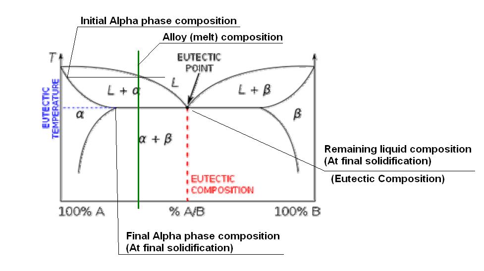
Trying to get the point accross simply, I will try to attach a sketch of a fictitious eutectic phase diagram. (I tried to get a W-Th or W-Zr phase diagram on the net, but no luck, without having to pay!) This one copied off Wikipedia!!

According to this diagram, the eutectic composition would be around 50% of B in A. I have indicated the composition of our alloy at around 25%. As this alloy solidifies (under equilibrium conditions - THIS IS IMPORTANT) once it goes below the top (liquidis) line, some of the liquid metal will start to solidify as an Alpha phase. The composition of the actual Alpha phase solidifying out at that initial solidification point can be read off by projecting a horizontal line to the Alpha line going down the left hand side. As the temperature decreases further, more Alpha phase solidifies, but the composition changes as indicated by the Alpha line going down the LHS. The remaining liquid composition tends to follow the liquidis line, so although the "average" composition is 25%, the Alpha phase will be much richer in element A, while the remaining liquid will keep getting richer in element B. Once it reaches the eutectic temperature, the liquid composition will now be 50% A in B, and is thus the eutectic composition, so will "instantaniously" solidify as the (Alpha plus Beta) eutectic phase.

Obviously the details of the transformation depends on the actual phase diagram, and in some instances, if there is just not enough of the "B" element present, the eutectic will not form. (e.g. In our sketch, when the %B drop below about 15% or so, (That sharp point on the Alpha line on the LHS.) no eutectic will be formed.

It is then also clear from this explanation why eutectics are "generally" not desirable in high temperature applications, because the part of the metal that solidified last at the eutectic composition will be the first to also melt upon heating, limiting the usefull temperature range of the alloy.

Hope this clarifies the issue.

Regards
Niekie
Parent - By electrode (***) Date 03-11-2012 12:02
Thank you, Niekie,
Perhaps you may read my former response again.
I have edited that, obviously whilst you have passed along this valuable input.
Cheers!
Parent - By Metarinka (****) Date 03-12-2012 07:30
Very good Information.
Parent - - By electrode (***) Date 03-12-2012 09:40 Edited 03-12-2012 10:06
"By the way, I have found something that could prove interesting eventually to this thread and the OP".

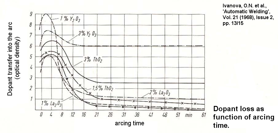
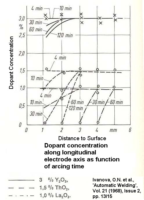
Well, that's marvellous. I can learn that the attachment function did work properly. The attached diagrams come from an investigation conducted some decades ago already. However, I do hope, they may prove helpful to the OP.  The research was on GTA electrode wear, depending on the electrode composition or dopant concentration, respectively. Spectral analysis was used for investigating tungsten electrodes of 4.0 mm in diameter (two electrodes - distance = 3 mm - were faced one to each other), and welding currents (AC) from 150 through 350 Ampere were applied. One trial was carried out at 300 Ampere welding current, loading arcing times of 4; 10; 30; 60 and 120 min. to the electrodes, see second diagram. Lanthanum- and Thorium oxides were found to 'quickly' disappear, relative to arcing time. Yttrium oxide however, was found to remain at the electrode surface, suggested due to its higher diffusivity (2 orders vs. Th and La). Yttrium oxide doped electrodes thus could be found to remarkably extend electrode durability vs. Thorium- and Lanthanum oxide types. To be honest, however. I did never see Yttrium doped electrode types commercially available, as yet. Anyway, I hope this helps.
Parent - - By bjbercaw (*) Date 03-21-2012 13:16 Edited 03-21-2012 13:55
Hey guys, very interesting thread. I am definately learning a lot from it.  We just ran some SEM tests on the "bearding" and I wanted to share a few pictures which you guys will probably find interesting.  The first shots were taken of the bearding while still on the taper of the electrode.  We then scraped off the bearding and reshot the flakes.  In both instances the composition of the bearding showed high levels of tungsten with some locations also showing thorium, Fe, Ti, & Ca.  I am still trying to wrap my head around the whole tungsten eutectic mechanism and how it could be occuring in our application.  I am going to have one of the electrodes cross sectioned and etched at the recommendation of Niekie to see what I see.  I am no metallurgist by any means, so I was wondering how I might be able to identify eutectics within the cross sectioned sample if they are present? Will it be obvious? Also do I need to use a special type of etchant? 

We are performing an informational x-ray immediately after weld that we have proven is sensitive enough to verify tungsten inclusions .015 or greater (which is around the size we were previously seeing when getting all of the rejects).  We have passed the last 9 production parts through this operation which is a little encouraging.  I have noticed the bearding was pretty much non existant on the electrodes used to weld these parts which is interesting.  We haven't really changed a whole lot from how we were welding them when we were seeing the inclusions previously.  We did change our bm cleaning procedure around a little and have been really paying attention to it, but other than that the only other thing we did was try to drop the wire as far away from the electrode as we could without it dragging.  Even this was relatively inconsistant between parts however, as mulitple adjustmants to the wire height are made throughout the length of the weld. 

As I am fairly confident after looking at these SEM results, that this "bearding" is where the inclusions we have been seeing is coming from, I would like to run some tests to attempt to reproduce the bearding.  My first thought was to drop the arc gap closer to the bm, but because I still do not fully understand the mechanism that is causing the bearding I thought you guys might have some better ideas or recommendations. 

Since its finally letting me attach things I went ahead and also attached some pictures of some of the oxides we have been seeing in the weld as well as bearding on the electrode during weld.  I also attached a short video where the arc hits an oxide from the previous toes and you can see material from the oxide/weld jump up and actually land on the side of the electrode (you have to look really close).  The last video shows the arc running over an oxide from the previous toe which causes the arc to flutter back and forth.  I thought maybe this is when the bearding could be falling into the puddle but thats only a theory.  The bm oxides are consistant throughout the weld no matter how much we clean the part.  We are getting ready to run a series of tests with the bm and fm to try to pinpoint what is actually causing the oxides. 

Keep the good posts coming.  Thanks

Brett

[img][/img]
Attachment: TungstenBeardingPictures.pdf - Tungsten Bearding Pics (328k)
Attachment: matjumpontoelectrode3.5.1237036.mp4 - Material Jump Onto Electrode After Hitting Oxide (0B)
Attachment: Weldingoveroxides.pdf - Welding Over Oxides (108k)
Attachment: 603-370322.28.12arcflutter.mp4 - Hit Oxide Arc Flutter (0B)
Attachment: oxideintrailingweldview.jpg - BM Oxides (342k)
Attachment: oxideintrailingweldview2.jpg - BM Oxides 2 (219k)
Attachment: bearding.jpg - Bearding (463k)
Parent - - By bjbercaw (*) Date 03-21-2012 14:05
here is a longer video of hitting an oxide

[vid=youtube][/vid]
Attachment: 603-370322.28.12arcflutter2.mp4 - Hit Oxide Arc Flutter 2 (0B)
Parent - - By bjbercaw (*) Date 03-28-2012 15:57
anyone have any additional thoughts after watching the vids and looking at the SEM results?
Parent - - By ozniek (***) Date 03-29-2012 12:08
Hi

Not sure if you have tried this, but may be worth a shot if you have not:

Use pure W electrodes. The doped electrodes have higher current carrying capacity, but their downside is their splintering behaviour after extended use. If you use a pure W, and increased the W diameter, and let it ball before commencing welding, (e.g. strike a high amperage arc in AC mode and maintain it till balling occurs.) maybe you will end up with less W inclusions in the weld. (Or maybe not!)

Regards
Niekie
Parent - By eekpod (****) Date 03-29-2012 15:38
After reading through these posts, now I know who the guys are that write those crazy scientific articles in the back of the AWS Welding Journal Magazine.. good luck to you all.
Parent - By electrode (***) Date 03-29-2012 16:23 Edited 03-29-2012 16:35
bjbercaw,

sorry for the delay.

Very well investigated - hats off!

Looking at your analyses, to me, there is NO eutectic observable; since I for myself am not aware of any W-Th-Fe-Ca eutectic to exist. I would suggest rather the electrode is losing Thorium as already mentioned in a previous post. Additionally to this I would suppose the Ca to arise from the parent material. That is, metal vapour from the weld pool seems to occur, partially precipitating upon the electrode surface, being already contaminated by Thorium decomposition products.

Short. I tend to agree with Niekie, trying some different electrode compositions. No dopants exisiting to diffuse from the inner electrode toward its surface, should lead to reduced bearding effects, at least.

I will attach some images arising from an interesting dissertation, dealing with plasma discharge modelling. They show the effect(s) already well-known and described by Niekie. You may recognise from this collection the ThO2 doped electrode proves worse, among the types considered. I hope that may prove helpful to you.

One final question, however. Are you mechanically preparing (grinding, turning, ...) the parent material prior to weld overlay? It's just that I'm wondering where these oxides, that you did mention, may come from. When the parent material is contaminated by its mill scale, that could explain a larger oxide cumulation to some degree. Just a thought, for what it's worth.

However, it may be that you did already mention this, within the amount of post and I did simply overlook that.

EDIT Corrected a typo.
Parent - By Metarinka (****) Date 04-11-2012 21:21
interesting results.    I believe your mechanisms are different than ours based on the evidence you presented so I would say low melt-point eutectics are most likely not an issue.

In regards to intentionally trying to increase bearding, reduced arc gap and increased heat input are direct ways, You can also downsize the electrode as that tends to increase current density.  Best of luck!
Up Topic Welding Industry / Technical Discussions / 2% thoriated electrode bearding

Powered by mwForum 2.29.2 © 1999-2013 Markus Wichitill