Not logged inAmerican Welding Society Forum
Forum AWS Website Help Search Login
Up Topic Welding Industry / General Welding Discussion / Carrier Pipe Double lined Diesel Project
- - By yojimbo (***) Date 01-10-2013 22:05
Just got called regarding a little diesel line project and would appreciate any input.  The job involve 3 lines, 2", 3", 4" sched 40 carbon steel.  The owner needs these lines, carrying diesel, to be run inside a secondary line for protection.  Each line will have approimately 6, 90degree LR elbows to make it work from point A to point B.  The contractor I'd be subbing to will have to "design" the system and working method.  Design in quotations as this will not need an engineers review.  Inspection will be limited to a low pressure air test of the diesel line if that.

The contractors superintendant is thinking of splitting some LR 90s lengthwise for the turns on the secondary pipe and welding them back up after diesel line is in.  I spent a few minutes laying out the center lines for a 4" carrier line inside a 6" secondary line and I am thinking the geometry isnt going to work because of the differences in radii.  The inside carrier line will not be concentric.  Possibly with a larger secondary line and/or short radius inside carrier fittings, but I am thinking there is a better/more established method.  We are surely not reinventing a wheel here and I would wager one of you guys has run into a similar problem with a known and accepted solution.

So before these guys burn too much time going in the wrong direction, can anyone point me in the right one.  How did you handle this, what is accepted practice.  The contractor is not a code shop, most of their work is threaded, I am their go-to welder guy and just try to keep them honest.  Which they usually appreciate.

Thanks in advance.
Parent - By Tommyjoking (****) Date 01-10-2013 23:47
Could the conincentric issues not be taken care of by simply a change in length of the carrier pipe?  If it is just an issue of meeting requirements of the sleeve??  To hell with the radius not meeting up properly....just go with spacing if your shoving this in existing.   Sorry if I am not understanding the problem correctly.
Parent - - By aevald (*****) Date 01-11-2013 03:15 Edited 01-11-2013 03:40
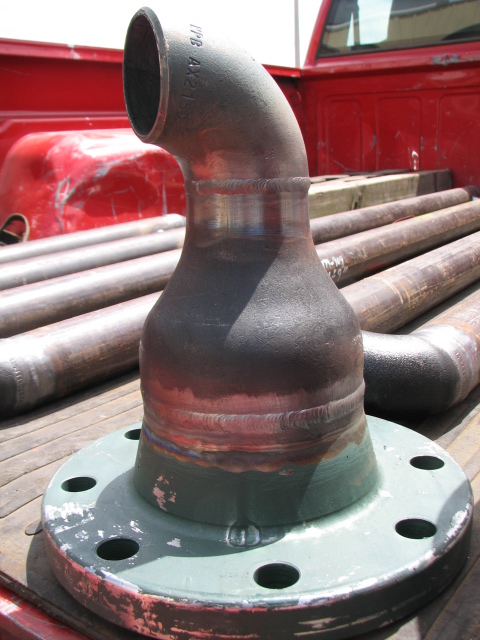
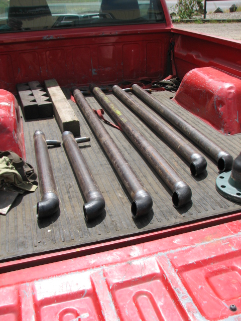
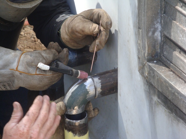
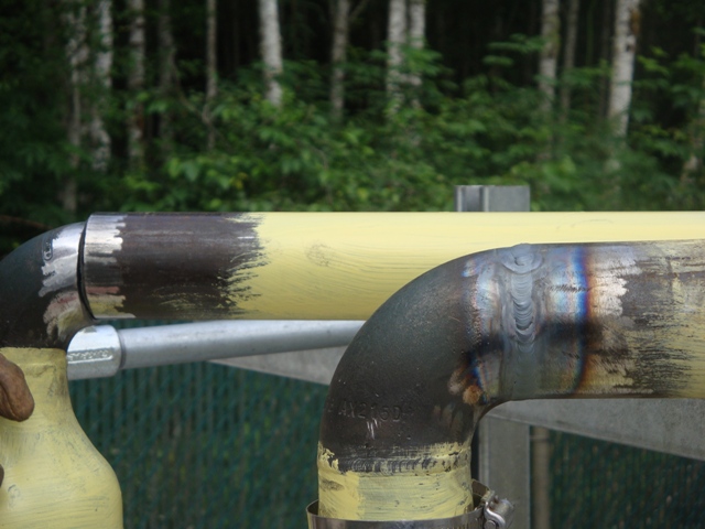
Hello yojimbo, reading your post pretty much mimics a job that I worked on in Northwestern Washington state. Fuel supply tank for a back-up generator system needed to meet certain environmental issues and compliance codes. I'll throw a few pictures your way. I have posted them on the forum here before,  just some time ago. Much of the success of a job like this depends upon prefabbing certain portions of the system and also having the individuals doing the screwed pipe portion of the work do their layouts and cut/threaded lengths correctly. Hope some of these pics help a little bit. Good luck and best regards, Allan

Edit: in some instances the elbows that were installed in the system were screwed on by inserting them into the weld ells and then feeding the pipe to them from the other end of the sleeve pipe sections. If the folks doing the install, either yourself exclusively or with others, such as in my case, pay attention to the big picture and plan out the runs you will be able to make a system like that work pretty well. The box that you see me crammed into was an external tattle-tale point with fuel sensors housed inside of it, the box also acted as a catch basin should the sensors, or flex pipe connectors have developed any leaks. This system was also tested with air for soundness. There were reducers that terminated the ends of the sleeving pipe to the actual screwed fuel piping at three points. Two of those three points were inside of that catch box, the other one was inside of the generator structure where the lines transitioned to the actual flex fuel lines that led to the generator. The start point of the system was bolted via the large reducers to outlet flanges on the fuel tank itself.
Parent - - By yojimbo (***) Date 01-12-2013 19:20
Aaevald-

Thanks for the info and pictures.  It looked like you were splitting the 90 ells on one of those photos to do what is referred to as "clamshell"?  Seems to be a common solution and what we are leaning toward.  I went to the pipe fitting supply store and lined up some short/long radius 90s to look at radii alignment and the contractor sent over a sketch of what he wants done and it looks to be the way we will be going.  Located a website that published it's shop drawings [reproducable] for jacketed piping and I had the radii backward- they use short radius 90s for the jacket pipe and long radius for the carrier pipe but in this situation at least, the configurations on the runs, simple riser to 90 to horizontal run to 90 to another horizontal run, the 3rd carrier 90 is going to have to field fit in position after sliding the jacketing pipe over the middle horizontal weld which makes squaring and leveling a bit more of a PITA.  With the carrier pipe jacketed there won't be any good way to square/level the fitting and it going to be closer to stovepiping the final fit than I like.  Can't stand having to cut a tack.  The jacketed 90s will have to be welded in after the carrier pipe is welded out and done in position.  It's all good though [how 2002 that sounds], just going to increase the price on the job some.  Think the count is abut 47 welds total including the split 90s, plus build some kind of support rack and get everything installed.  A lot of times I just do the work for these guys hourly when they can't/won't supply a dimensioned diagram [which is often] and they need me to do all the field measureing, which I prefer over trusting their mistakes, and maybe cap it with a not to exceed price.  They grumble some, but quietly, and the owner knows I have to make a living too although he sometimes acts aghast.  One thing working to my advantage is that most of the guys who work for themselves don't have a pipe fabrication/welding backround and stick to general fabrication/light structural/ornamental.  I do a lot of that as well but my backround as a rig welder/pipefitter let's me do this kind of work succesfully on these small jobs without the expense of doing it as a primary function which would include heavy insurance costs, R stamping, code documentation, licensing and all the overhead expenses a mechanical outfit like JH Kelly or such incurs.  Of course I wouldn't mind being in those shoes if I had the brains to wear them, but that just aint the case.
Parent - - By aevald (*****) Date 01-12-2013 19:35
Hello again yojimbo, it sounds like you are going to be welding "all" of the piping components of your job? I was working with a couple of fellas who were screwing all of the fuel piping together and slipping on the various containment piping for me to fit and weld together as we went along. Yes, we did split the elbows that were used for the various connection points. I would "tack" the ells to the inside of a piece of angle iron and then carefully set them up in a horizontal band saw and saw them in half. Worked pretty well, also match-marked the pieces to allow for correct matching before welding them back together. Most of the time the split ells could be tacked together over the supply piping screwed ells before they were fitted to the various ends of sleeving pipe that needed to be welded together. Having the "reducers" on the ends actually allowed for enough play in the system to provide access for screwing the supply piping together rather readily. Welding the supply piping would certainly pose a bit more of a challenge I believe, yet it can still be done. As you mentioned though, don't cut yourself short on bid hours for this project. Good luck as you move forward and if you can please share the progress with some pictures and correspondence. Best regards, Allan
Parent - - By yojimbo (***) Date 01-12-2013 20:00
Allen,

Wow, fast response.  Wasn't even finished with the other replies.  Yeah. I was thinking about how I was going to split the 90s.  Want to do them in the horizontal bandsaw at the shop but hadn't figured out a good clamping system yet, and don't know if the 6" jacket pipe 90 will fit in on my 7 X 12 bandsaw anyway.  Need to give this more thought.  The smaller 3 and 4inch 90s should be able to be made to work, possibly do them vertically.  Yeah, I will be doing the work alone, there's usually a guy to buff the welds and such if I need it, but you waste so much time in short term training it isn't usually productive.  The 4" carrier line with the 6" jacketing is going to be heavy enough to warrant a second set of hands to install but I'll just have the supe on the forklift and do the rigging myself.  He tells me this is going to be done in about 3 weeks- early Feb in WA state is always my preferred choice for outside field fabrication- but I will prefab 90s and randoms and as much as I can in the shop.  He mentioned it being a 2 day job, sort of like trying to get a fish to bite [here fishy, fishy] and I told him he was looking at 3 plus more likely, but like I said, they grumble some but not too loudly, and after a 7 year relationship with them they know I don't gouge and haven't screwed up on them yet.  The job is on the North side of Seattle though and I'm down by Tacoma which as you know means travelling through the belly of the beast and incumbent traffic horror.  I'll include a mobilization on the quote and use it for a 2 day motel stay rather than driving through that muck, which they won't like but it's a job cost that I won't absorb.  Did you make the move to FLA or still in the NW?
Parent - By aevald (*****) Date 01-12-2013 21:59
I happened to notice that you were online and when I clicked on this thread I noticed your reply. Haven't made a move yet, the wife calmed down about some of the issues that she was upset over and her real estate work started clicking rather well so we're still in WA. Haven't posted on here much either, my teaching job has been keeping me hopping in good ways. We qualified for some special funding that was offered up by the legislature and ended up with $250,000 to put into the welding program at our school. When I get a chance later I will be sharing a lot of this on the forum, both written and pictorial.

You are definitely working with some larger sleeving pipe and fuel line than the little project that I included here. I believe your saw will handle the 3" and 4" ells, but those 6" ones would probably not fit unless you were able to orient the ends of the inside radius flat onto the bed of the saw and somehow hold it upright and clamp the upper radius ends between the stops of the saw. If you end up thermal cutting them you may wish to consider how you can keep the dross from sticking to the opposite side of the cut on the inside of the ell. If you can somehow roll/bend a piece of flat bar to roughly the center line radius (1/4" or so thick by maybe 5 1/2" to 6" wide) to insert inside of the ell while you are cutting, it would likely provide a barrier to prevent what I was describing above. Look forward to a rundown on your progress. Good luck and best regards, Allan
Parent - By ctacker (****) Date 01-12-2013 23:20
Took me 2 hours from the south portal of the new Viaduct tunnel job to get to Tacoma yesterday, I hate driving the Seattle area.
Parent - - By thewelder (***) Date 01-11-2013 04:48 Edited 01-11-2013 09:06
hi yojimbo im Jaime thewelder here are some pix's of the work i did on a diesel lines inside of the secondary lines on a back up generators on a AT&T data analyze site a few months ago, the contractor made the desing with out ELLS.
Attachment: WP_001167.jpg (119k)
Attachment: WP_001168.jpg (114k)
Attachment: WP_001169.jpg (107k)
Attachment: WP_001170.jpg (136k)
Attachment: WP_001171.jpg (99k)
Parent - - By yojimbo (***) Date 01-12-2013 19:29
Jaime,

Thanks for the response and pictures.  Small world.  This project is for AT&T as well.  We wont be running 2 lines in the jacket pipe, just 1 line per run.  The mitered turns on the jacket pipe you guys did works well, and allows access to the carrier pipe welds at the 90s.  I think we'll be using short radius 90s for the jacketing and splitting them to clamshell the turns although I am going to try and share the pictures you provided with the contractor to let him decide if it would be more cost effective.  The superintendant would prefer the look of 90s for the jacket pipe over the mitered turns, but may decide otherwise after seeing how your project turned out.  It would reduce job costs for him, make my life a little easier and would look good.  Thanks again.
Parent - - By thewelder (***) Date 01-12-2013 21:44 Edited 01-12-2013 22:16
yojimbo,

no problem, this was at AT&T on Selma Cali. site, 15 min, So. of Fresno ca. where is your job at? i have more pic's but those are on my Ipad, Ill try to upload it may be Monday, some are mitered others are with 90 Ell (no cuts) the only problem is you doing the primary and secondary lines at the same time and to have then center just tack a pcs os 1"X 1/8 X ID (of the secondary pipe) flat bar on the primary pipe about 12" before and after the Ell. no weld to secondary for movement here are a hand made pic's, hope it help. i add an other pic. (sorry for the size) if you see around you can see the flat bars
Attachment: tack..jpg (19k)
Attachment: photo.JPG (656k)
Attachment: pipeintopipe.JPG (91k)
Parent - - By aevald (*****) Date 01-12-2013 22:02
Jaime, nice work! Are you staying pretty busy these days? I do believe that the economy is getting a bit better and busier these days, hope it keeps up. Best regards, Allan
Parent - By thewelder (***) Date 01-12-2013 22:07
Tank you, the work is going up, more bit going out then the last years for sure.
Parent - - By spgtti (**) Date 01-11-2013 12:13
The jacketed (10" supply, 24" return ) piping I worked on used a much larger containment line to work the supply fittings through. All they did was work the supply 90 with pipe stubs long enough to fit through the containment 90 and be able to make the supply butt welds, and tack them to round bar inside the containment lines to keep everything centered. Then we had split pipe to connect between the containment 90 and piping, this part was a fit-up PITA)
If I had the chance to engineer it I would size the containment piping large enough to run the supply piping with pipe stubs, on to get the weld out and away from the edge of the containment 90, tack everything centered in place using round bar welded to the inside of the containment pipe to keep it centered and ease fit up, and find some pipe with an I.D. close to the O.d. size of the containment pipe  to slide over the open space where you made the supply weld.
Parent - - By yojimbo (***) Date 01-12-2013 19:38
spgtt-

Good points.  A website I downloaded some shop drawings from for jacketed pipe makes the same sugestions and calls out short radius 90s for the jacket pipe @ equal to carrier pipe size plus 4" for pipe sizes 8" through 12" and larger.  They use reducers to close off jacket pipe to carrier pipe and a ring plate, fillet welded to the opening when ID/OD dimensions exceed weldable tolerance.  If we split the 90s to clamshell the jacket pipe it is going to be some PITA fitting in the field, but I'm pretty sure I wont be needing to split any jacket pipe longitudinally just the 90s.  Did you have any issues with the 90s springing out of round after splitting them?  You know the way a length of pipe will when you split it lengthwise?  Let me know.
Parent - By spgtti (**) Date 01-13-2013 13:38
We never split any 90s, and as you said the containment pipe terminated at a concentric reducer. If the carrier was way off the containment pipe size we used plate to cap the reducer just as you'd said. As long as you allow enough of a size difference between the 2 lines you can move the carrier around inside the containment with pipe stubs welded to your tees and 90s and then tack the carrier in place on the round bar to lock in the fits.
Up Topic Welding Industry / General Welding Discussion / Carrier Pipe Double lined Diesel Project

Powered by mwForum 2.29.2 © 1999-2013 Markus Wichitill