Not logged inAmerican Welding Society Forum
Forum AWS Website Help Search Login
Up Topic American Welding Society Services / Technical Standards & Publications / CJP Groove Welds for Tubular Connections Questions
- - By erazorzedge (*) Date 08-14-2013 16:19
Hi,

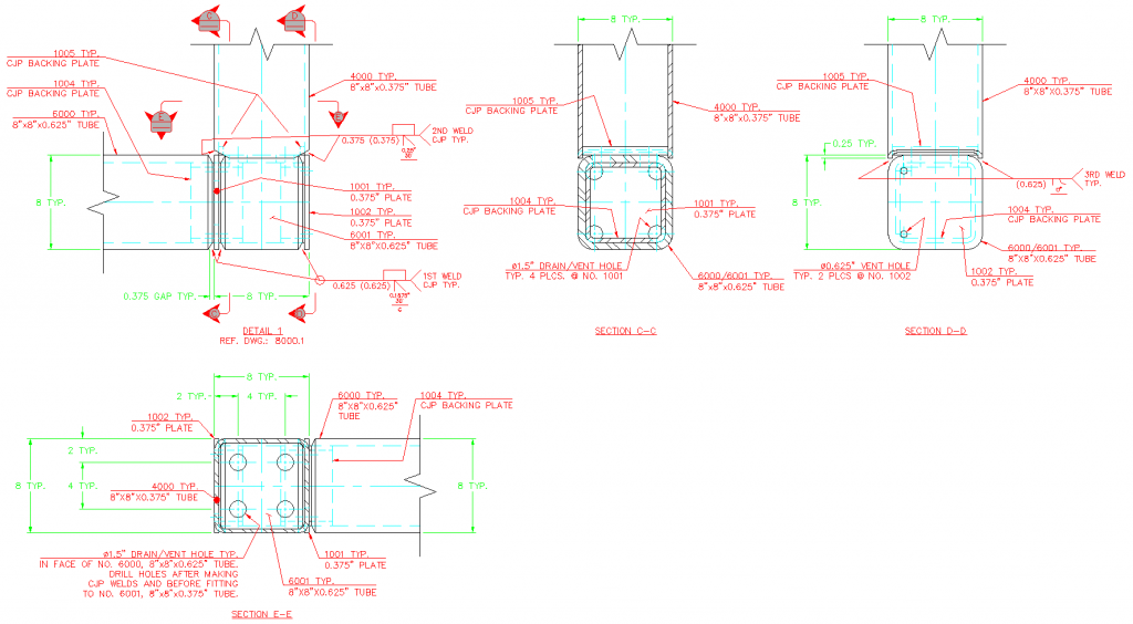
I'm working on a project in which the contract drawings depict a box tube structure with moment connections where the vertical post, transverse member, and longitudinal member intersect (see attached image). I have a few questions regarding the exact type of joint(s) that are shown & what test to have our welders qualified to, and how to interpret a certain clause when it appears to be in conflict with a table. I'm also using the D1.1 2010 code book.

Firstly, when looking at the attached drawing, would any of the CJP weld joints be considered T-, Y-, K- Connections for tubular connections? If not, would they be considered a CJP groove weld in a tubular connection at all?

Secondly, looking at clause 4.27, it lists a breakdown of what details to use for the welder/operator qualification tests for CJP groove welds for tubular connections. Number 3 states "CJP groove butt joints or T-, Y-, K-connections with backing in box tubing. Use Figure 4.24(B) in pipe (any diameter), plate or box tubing." From what I comprehend, this clause states that we can have our welders qualified to a 3G & 4G plate test using the detail from Figure 4.24(B). If that is true, then it seems to directly conflict with Table 4.10 which states that the only allowable test position for CJP groove weld T-, Y-, K-connections in box tubing is the 6GR (figures 4.27 & 4.29) test position. This would seem to preclude using any plate test to qualify a CJP T-, Y-, K-connection in box tubing. Can someone clarify this form please?

I was also looking at the commentary (C-4.27) which talks a lot about CJP T-, Y-, K-connections in box tubing and the need to make sure the welders can wrap the corners effectively and that a test to Figure 4.29 is required; however, I'm not sure if this applies to our scenario based on other statements as I pointed out above. To add to my confusion, I was speaking with a few people (different companies) regarding doing the testing of our welders for this project, and one person told me that because we have backing bars inside the tube, it some how makes these joints more like plate and shouldn't have any limitations placed on it like a CJP T-, Y-, K-connection in box tubing would.

I would appreciate any help on this.

Eddie

Parent - - By 803056 (*****) Date 08-14-2013 17:06
Attach your sketch as a pdf so we can expand it to see the details.

Al
Parent - - By jwright650 (*****) Date 08-14-2013 17:42
Al, Click the pic:wink:
Parent - - By 803056 (*****) Date 08-14-2013 18:15
Thanks John. I just learned something new.

The welding symbol for the flare bevel groove is wrong. The tube is 3/8 inch wall, so the max. CJP is only 3/8. The flare bevel symbol also requires the radius of the round edge. Check AWS A2.4 for the requirements of the welding symbol and check AWS D1.1:2010, Table 2.1 for the maximum size of the PJP flare bevel groove when no root opening is used. You can also look at figure 3.3 page 92 if you decide to go with a PJP.

If you are trying to approach the details as plate rather than tubulars, you need to check the prequalified joint details to verify you conform to the required groove angles, root openings, etc. As shown you will be in trouble as you wrap the weld around the corner radius, i.e., there is no backing for a good portion of the corner so the weld root is unsupported (back to a CJP without backing).

Fitting a backing bar around the inside of the tubular is difficult to say the least. Consider using a thick plate cut and ground to conform to the inside of the tube. The cost of the plate is much less than the labor involved in making a bar conform to the inside shape of the tube. Let the plate extend past the end of the tube as if it were a backing bar.

If the joint are fully backed, the welders can be qualified using the standard plate tests. Without being fully backed, the welders will have to qualify on the T,Y, ad K test assembly.

Best regards - Al
Parent - - By jwright650 (*****) Date 08-14-2013 18:43

>Consider using a thick plate cut and ground to conform to the inside of the tube.


That is the way we approach this, we use a 1" thick plate and it covers the joint nicely. We have used a 1/4" x1 bar continuous(FullPen @ the butt joint) around the inside but the fitting time is about double vs burning out a plate and grinding the edges to fit.
Parent - By erazorzedge (*) Date 08-14-2013 20:53
I realized a couple days ago that making a "doughnut" out of some 0.75" plate to fit inside the tube would be a lot easier than trying to form a piece of flat bar to a specific radius. I just haven't applied it to the drawings yet as it's not ready to fabricate. Thanks for the tip though.
Parent - - By erazorzedge (*) Date 08-14-2013 20:51
Thanks for the reply Al.

We're using the FCAW-G process here by the way, so keep that in mind for all the info I'm pulling out of the code book.

For the flare-bevel groove weld (PJP), the joint configuration is as shown in AWS D1.1:2010, Figure 3.3, Page 84 (inches) and the "Side Matched" detail in Figure 3.5, Page 118. According to Figure 3.3, T1 = 0.625" (#'s 6000 and 6001) and since it's box tube, note "m" states that "r shall be two times the wall thickness", so r = 1.25" and (E) = 0.78125". I had originally not seen the note "m" stipulations, so as it's shown above r = 0.9375" and (E) = 0.5859375", or as I rounded up to the nearest sixteenth, 0.625". Also, T3 = 0.375" (# 4000), but I wasn't aware that it affected the (E) value. As for Table 2.1, it states that for flare-bevel groove welds, the effective weld size (E) shall be 5/8*r, but then it refers to clause 2.4.1.4 which states that for box tubing, r = 2*Wall Thickness (which is what Figure 3.3 and note "m" state). I'm trying to stay within the prequalifed realm for the joint designs, and as such, if I call out an effective weld size that does not correspond to what is described in Table 2.1 or Figure 3.3 for flare-bevel groove welds, will it still be considered prequalified?

I also see in AWS D2.4:2012 that the D and (S) are shown sometimes and other times not. But what I don't see is that it is a requirement to place both the D and the (S) in the weld symbol. Can you tell me where that is stated?

Onto the CJP welds. For what I have labeled as "2nd weld", the contract drawings labeled the welding for the joint as "CJP T&B". Top and bottom would be left and right as shown on Detail 1 of the drawing above. Do you have to wrap the corners if the contract drawings stipulate T&B for a T-connection?

Also, I'm not trying to approach this as plate rather than tube; however, a person at a welder certification company had told me that it's basically plate and that qualifying the welders to a plate test, such as 3G, would qualify our welders to make these welds as shown. So do the joint connections I have detailed abide by the CJP goove weld T-,Y-,K-connections for box tube or not?

Can you tell me where in the code book it states that fully backed joints only require a plate test?
Parent - - By 803056 (*****) Date 08-14-2013 22:00 Edited 08-15-2013 03:27
For the flare-bevel groove weld (PJP), the joint configuration is as shown in AWS D1.1:2010, Figure 3.3, Page 84 (inches) and the "Side Matched" detail in Figure 3.5, Page 118. According to Figure 3.3, T1 = 0.625" (#'s 6000 and 6001) and since it's box tube, note "m" states that "r shall be two times the wall thickness", so r = 1.25" and (E) = 0.78125". I had originally not seen the note "m" stipulations, so as it's shown above r = 0.9375" and (E) = 0.5859375", or as I rounded up to the nearest sixteenth, 0.625". Also, T3 = 0.375" (# 4000), but I wasn't aware that it affected the (E) value. As for Table 2.1, it states that for flare-bevel groove welds, the effective weld size (E) shall be 5/8*r, but then it refers to clause 2.4.1.4 which states that for box tubing, r = 2*Wall Thickness (which is what Figure 3.3 and note "m" state). I'm trying to stay within the prequalifed realm for the joint designs, and as such, if I call out an effective weld size that does not correspond to what is described in Table 2.1 or Figure 3.3 for flare-bevel groove welds, will it still be considered prequalified?
I do not believe it is considered prequalified if the welds are specified to be larger than those indicated by Table 2.1. The contractor has the option of qualifying the WPS and performing macro-etches to verify the larger weld size can be obtained. You can refer to clause 3.10 to verify I am not chasing my tail. Check your root opening and groove angles to verify they meet the prequalified groove details of Figure 3.4. At first glance it seemed some of the groove angles and root openings are noncompliant. That being the case, the fabricator would have to qualify the WPS.

I also see in AWS D2.4:2012 that the D and (S) are shown sometimes and other times not. But what I don't see is that it is a requirement to place both the D and the (S) in the weld symbol. Can you tell me where that is stated?
Forgive me, I don't have my A2.4:2012 on my desk, but I do have the 2007 edition. On a leap of faith that the figures are the same in both editions, take a look at Fig. 22. A2.4 is using the dimensions: S=radius and (E)=weld size. Reviewing the figures in D1.1 and A2.4 I notice a discrepancy; D1.1 does not indicate the radius of the flare. Being a belt and suspenders type of fellow and to ensure everyone is on the same page, I list the radius and the weld size as indicated in A2.4.

Onto the CJP welds. For what I have labeled as "2nd weld", the contract drawings labeled the welding for the joint as "CJP T&B". Top and bottom would be left and right as shown on Detail 1 of the drawing above. Do you have to wrap the corners if the contract drawings stipulate T&B for a T-connection?
My understanding is that the corners must be welded continuously with the weld terminations and initiation points within the flat faces per note 7 page 118 or D1.1:2010. It appears all four sides of the box tubes are welded in your design. The corners are the most rigid portion of the connection. The flat faces are very flexible, thus the corners are the "hot spots" where the stresses are the highest. It would seem to me that you would do something to ensure the welds are sound in those corners, i.e., no starts and stops in the corner radius.

Also, I'm not trying to approach this as plate rather than tube; however, a person at a welder certification company had told me that it's basically plate and that qualifying the welders to a plate test, such as 3G, would qualify our welders to make these welds as shown. So do the joint connections I have detailed abide by the CJP groove weld T-,Y-,K-connections for box tube or not?
The special welder qualification tests required by AWS D1.1, refer to Figures 4.27, 4.28, and 4.29, are required when the welds details require CJP without backing. From what I can see, all your groove details include backing, so I would side with the testing lab in this case and qualify the welders using plate as shown in Figure 4.24B [referring clause 4.27(3)]. 

Can you tell me where in the code book it states that fully backed joints only require a plate test?
See response to previous question. Figure 4.24B [referring clause 4.27(3)]

I hope I answered all the questions and I hope I'm right. There are several experts here that will jump in and help us better understand the requirements for tubulars. It isn't often (I can say NEVER) I encounter a design that actual meet the design requirements for tubular structures.

Good luck - Al
Parent - - By erazorzedge (*) Date 08-15-2013 14:36
I still have more questions Al. :smile:

I do not believe it is considered prequalified if the welds are specified to be larger than those indicated by Table 2.1. The contractor has the option of qualifying the WPS and performing macro-etches to verify the larger weld size can be obtained. You can refer to clause 3.10 to verify I am not chasing my tail. Check your root opening and groove angles to verify they meet the prequalified groove details of Figure 3.4. At first glance it seemed some of the groove angles and root openings were noncompliant. That being the case, the fabricator would have to qualify the WPS.

Forgive me, I don't have my A2.4:2012 on my desk, but I do have the 2007 edition. On a leap of faith that the figures are the same in both editions, take a look at Fig. 22. A2.4 is using the dimensions: S=radius and (E)=weld size. Reviewing the figures in D1.1 and A2.4 I notice a discrepancy; D1.1 does not indicate the radius of the flare. Being a belt and suspenders type of fellow and to ensure everyone is on the same page, I list the radius and the weld size as indicated in A2.4.


You had originally stated that the weld symbol for the flare-bevel groove weld is wrong, since the intersecting box tube (T3 according to D1.1:2010 Figure 3.3, page 84) has a wall thickness of 3/8". If I do the calculations per Figure 3.3, page 84, as I showed before, the effective weld size is 0.78125", but that is more than the T3 thickness. Is there a something in the code book that states that the effective weld size shall not exceed the T3 thickness? If so, will it still be prequalified?

My understanding is that the corners must be welded continuously with the weld terminations and initiation points within the flat faces per note 7 page 118 or D1.1:2010. It appears all four sides of the box tubes are welded in your design. The corners are the most rigid portion of the connection. The flat faces are very flexible, thus the corners are the "hot spots" where the stresses are the highest. It would seem to me that you would do something to ensure the welds are sound in those corners, i.e., no starts and stops in the corner radius.

I understand the point about making the starts/stops in the flat vs. the corners of the box tube; however, if the contract drawings state that only two sides of the box tube be CJP, do you need or have to carry the CJP all the way around the corners? Or does welding the flat face portion box tube effectively meet the designers intent of "CJP Top & Bottom"?

The special welder qualification tests required by AWS D1.1, refer to Figures 4.27, 4.28, and 4.29, are required when the welds details require CJP without backing. From what I can see, all your groove details include backing, so I would side with the testing lab in this case and qualify the welders using plate as shown in Figure 4.24B [referring clause 4.27(3)].

The only problem with clause 4.27 (3) saying that you can qualify a welder by doing a test on pipe (any diameter), plate, or box tube, is that Table 4.10 (referring clause 4.19.1) doesn't list a "qualified for" position for Box Tube, CJP, T-, Y-, K-Connections on anything other than a 6GR test plate. It doesn't even have a note that should say something like "Testing on plate, pipe, or box tube using Figure 4.24(B) will qualify for Box Tube CJP T-, Y-, K-Connections utilizing backing in any position." Since Table 4.10 doesn't say that a welder is qualified for a position, am I supposed to assume that because clause 4.27 (3) states that it's acceptable, the welder is qualified for whatever position (and under) he/she tested on for Box Tube CJP T-, Y-, K-Connections utilizing backing? That seems like a rather large assumption if that's what one is supposed to do.

I really appreciate your help so far. I look forward to other people's responses as well. Thank you.

Eddie
Parent - - By jwright650 (*****) Date 08-15-2013 14:42

>I look forward to other people's responses as well.


I've been wanted to dig into this thread a bit and read it through before responding...I just haven't had the time. I have been covered up UT'ing full pen WF outriggers and full pen stiffener plates. These columns are loaded down with work. Some of these columns have 68 or more full pen joints each and the fitters/welders have 2-3 on each of their tables, and some of these are thick enough to require UT scanning with multiple angles.
Parent - By welderbrent (*****) Date 08-15-2013 14:46
You too.  We have some going with over 80 CJP's.  Only wish I were already working on my UT certs, boy the hours I could get here!  :lol:

Have a Great Day,  Brent
Parent - - By 803056 (*****) Date 08-15-2013 14:55 Edited 08-15-2013 15:04
You had originally stated that the weld symbol for the flare-bevel groove weld is wrong, since the intersecting box tube (T3 according to D1.1:2010 Figure 3.3, page 84) has a wall thickness of 3/8". If I do the calculations per Figure 3.3, page 84, as I showed before, the effective weld size is 0.78125", but that is more than the T3 thickness. Is there a something in the code book that states that the effective weld size shall not exceed the T3 thickness? If so, will it still be prequalified?

Paraphrased: Clause 2.4.1.4 states when there are two different radii, the smaller radius is the basis of determining the size of the weld.

I understand the point about making the starts/stops in the flat vs. the corners of the box tube; however, if the contract drawings state that only two sides of the box tube be CJP, do you need or have to carry the CJP all the way around the corners? Or does welding the flat face portion box tube effectively meet the designers intent of "CJP Top & Bottom"?

I would pose that question to the Engineer for resolution.

The only problem with clause 4.27 (3) saying that you can qualify a welder by doing a test on pipe (any diameter), plate, or box tube, is that Table 4.10 (referring clause 4.19.1) doesn't list a "qualified for" position for Box Tube, CJP, T-, Y-, K-Connections on anything other than a 6GR test plate. It doesn't even have a note that should say something like "Testing on plate, pipe, or box tube using Figure 4.24(B) will qualify for Box Tube CJP T-, Y-, K-Connections utilizing backing in any position." Since Table 4.10 doesn't say that a welder is qualified for a position, am I supposed to assume that because clause 4.27 (3) states that it's acceptable, the welder is qualified for whatever position (and under) he/she tested on for Box Tube CJP T-, Y-, K-Connections utilizing backing? That seems like a rather large assumption if that's what one is supposed to do

When there’s a discrepancy between the text of a clause and an accompanying table or figure, the written text takes precedence.

I hope this helps you resolve the issues at hand. I was counting on Brent (notice the "r") and John would jump in to provide a sanity check on this one. Tubulars are a *****. There is no other way of saying it.

From what I understand the section on tubulars was developed in response to the offshore oil industry's request to provide a rational basis of design and fabrication of offshore tubular structures. Considering the harsh nature of the offshore environment some of the requirements may be assuming conditions that are not consistent with a structure that only experiences static loads. That's where the Engineer has to step up to the plate and provide additional direction to the detailer an the fabricator if the structure is going to be both  functional and economical.

Best regards - Al
Parent - By erazorzedge (*) Date 08-15-2013 15:35
Paraphrased: Clause 2.4.1.4 states when there are two different radii, the smaller radius is the basis of determining the size of the weld.

That specific paraphrasing starts off by stating "For flare-V groove welds..."; our connection is a flare-bevel so that shouldn't apply. Are there any other clauses that you know of which would tell you to use the thinner material or the smaller radius?

I would pose that question to the Engineer for resolution.

I've already submitted these drawings as shown and they reviewer didn't have an issue with the welded joints, but then my joints details don't specifically limit the CJP to the face of the intersecting tube. I'll have to ask the question then... oh how my bosses love questions when the answer (to them) is "whatever is easier for us".

When there’s a discrepancy between the text of a clause and an accompanying table or figure, the written text takes precedence.

I've read that before on these forums; however, the text of clause 4.19.1.1 Welders and Welding Operators (Table 2.10 refers to the parent clause, 4.19.1 Production Welding Positions Qualified) states "The qualified production welding positions for welders and welding operators shall be in conformance with Table 4.10." That text is pretty clear, but the table is unclear when used with clause 4.27(3). I've placed a call to Brian McGrath over at AWS and asked him about this and he said he would get back to me because it is unclear, but nothing from him yet. It seems like this would have been clarified in one of the revisions of the code book, but maybe it's just unclear to a novice like myself.

Thanks again.
Eddie
Parent - - By welderbrent (*****) Date 08-15-2013 17:08
Due to an in company disagreement last week, I have been really tied up.  I have been following this but have not had much time to really dig into it and it isn't one of those things that just jumps out at me. 

Besides, we have the world renowned 'Al' working on it.  :lol:  Looks like he is doing quite well to boot. 

But, I will see if I can take some time and review and give my two tin pennies worth here in a bit.  Thanks for the vote of confidence as well as the 'r'.  (inside joke for those outside the loop; I think he is buttering me up)

Have a Great Day,  Brent
Parent - - By welderbrent (*****) Date 08-15-2013 19:05
AAAAGGGGGHHHHH!!!

Would you guys just use the joint designations instead of page numbers :confused: ?  I'm stuck at a cubicle 100 miles from home with a D1.1 2008!  page numbers are not the same.  With Figure #'s, Table #'s, and joint designations I might be able to make more sense of this.

I'll have to look at it later when I can get to my 2010.  I'm just ranting, don't intend for either of you to go back and change anything.

Thus far, I concur about the misused/wrong information on the flare bevel groove.  But, Al, isn't Table 2.1 'Effective Size' for design calculations for strength of the joint?  Not really a 'maximum' size table. 

I'll go back to reading now. 

Have a Great Day,  Brent
Parent - - By 803056 (*****) Date 08-15-2013 20:28 Edited 08-15-2013 20:32
Remember I mentioned the sanity check? This is a good example of when a sanity check is needed. I don't know how I got side tracked to clause 3.10 which is talking about plug and slot welds. Again, I'm caught with my head up my own butt. The question was with regards to flare groove welds, so let me take another stab at it.

Prequalification is covered by clause 3, I believe we can all agree on that point. Moving on to clause 3.12.2.1 (3), it talks about the minimum (prequalified) weld size of the flare groove details BTC-P10 and BTC-P11 being based on Figure 3.3. The values listed by in the figures are consistent (the same as) those listed in Table 2.1. I believe there is an error here or I am missing something. If you refer back to clause 2.4.1.4, the weld size of a flare bevel or a flare V-groove weld is as per Table 2.1. My understanding is that if the designer wishes to take credit for a larger weld size than listed by Table 2.1, the contractor must qualify the WPS to demonstrate the larger weld size specified can be achieved (refer to clauses 2.4.1.4 and 4.11.5). Yet this is not what clause 3.12.2.1(3) is saying, so I am confused. Is the size "(E)" given in Figure 3.3 for BTC-P10 and BTC-P11 minimum acceptable sizes or are they the maximum weld sizes?

It looks like another inquiry to the D1.1 committee is in order. I believe I have two pending already.

Best regards - Al
Parent - - By erazorzedge (*) Date 08-15-2013 21:47
I think I might have an answer for you.

So, clause 2.4.1.4 says the effective weld size for flare-groove welds shall be as per Table 2.1. Clause 3.12.2.1(3) says that the minimum weld sizes shall be calculated from Figure 3.3.

Now, Table 2.1 lists the effective welds size for flare-bevel groove welds (FCAW) as 5/8*r. Theoretically (or at least from what little I've seen), the outside radius is roughly 2x the material thickness, which I'll say is 0.375". So the effective weld size should be 0.625*(2*0.375) which equals 0.46875".

Using the calculations from Figure 3.3, joint designation BTC-P10-GF, they give a formula to determine the radius which is r = (3*T1)/2, with a note (m) which states that r shall be two times the material thickness for rectangular sections. When utilizing box tubing, the effective weld size is the same as Table 2.1, 5/8*r, but when utilizing bent/formed plate, it should be less. So doing the calculation for bent/formed plate using the same material thickness, the minimum effective weld size should be 0.625*((3*0.375)/2) which equals 0.3515625".

Since the text says that prequalified flare-bevel groove welds are per Figure 3.3 and the calculations from that figure yield an effective weld size equal to or less than the effective weld size given in Table 2.1, then I would say that the two portions of the code are in agreement. The exception only being the note under clause 2.4.1.4... "except as allowed by 4.11.5. In that case you would have to write up a PQR to verify that your larger effective weld size is being achieved.

But I see where I screwed the pooch on that flare-bevel groove weld symbol... Figure 3.3 lists the thickness of T1 as 3/16" minimum and for a T3 scenario (like a side-matched box tube), T3 needs to be equal to T1 minimum. So since I have a 0.375" wall tube (T3) intersecting a 0.625" wall tube (T1), it's basically not a prequalified weld. So I guess I have to do some sort of testing for this joint. Dang it.

Thanks for helping me see that.
Parent - By 803056 (*****) Date 08-16-2013 18:28
Just make sure you take the welding process into consideration. I had contractor take credit for the largest weld size without considering the process or position.

Best regards - Al
Up Topic American Welding Society Services / Technical Standards & Publications / CJP Groove Welds for Tubular Connections Questions

Powered by mwForum 2.29.2 © 1999-2013 Markus Wichitill