Not logged inAmerican Welding Society Forum
Forum AWS Website Help Search Login
Up Topic Welding Industry / General Welding Discussion / manipulating welds
- - By whatever Date 09-19-2014 13:18
Good morning
I have a question on manipulating weld.
We use GMAW weld process with C10 gas mixture and .045 wire both metalcore and solidwire with M5 gas mixture.
We weld steel and structural steel from 10gauge to 1". We do have tubular with attachments also.
The company and QA department want stringer Beads. Any WPS's in place state stringer bead.
We have several welders that insist manipulating is better and easier. Most of them whip but do have a couple that oscillate.
Whipping is not consistent between all welders using this process.
I would appreciate any information and recommendations you have on manipulating of welds
The company does also do some aluminum and stainless steel welding GMAW process.
Parent - - By Lawrence (*****) Date 09-19-2014 14:01
Welcome to the forum Whatever !

For structural steel and GMAW spray transfer (I am assuming you are doing this by your .045 wire and gas mix)

Several points to be made.

1.  Any time the operator "whips" the gun, the electrode wire moves away from the leading edge of the puddle and back into the built-up puddle.  When the arc is directed to the back half of the puddle it is "cushioned" by the already deposited filler and penetration is reduced.  This technique will also have a tendency to reduce sidewall fusion.  The only time this manipulation can have a beneficial effect is if the operator is attempting to "reduce" penetration or burn-thru on gage materials.   I support the practice of requiring stringer beads for spray transfer of D1.1 work.
A single pass fillet of 3/16", 1/4" or 5/16" can be produced with .045 filler and up to 290 amps (400 ipm approx.) with a straight 10-20 degree push and no whipping on material from 1/8" to unlimited thickness without burn thru.

1a, Welders have a tendency to want to whip the gun for several reasons..  First because they have a voltage setting that is too high and the whipping backfills undercut on the top leg of a fillet.   Secondly they like the "signature look" of a rippled bead.   The answer to this is that the voltage can be reduced to eliminate undercut and that the customer wants a "corporate" signature on every weld.   Having different looks on welds only gets unwanted attention from 3rd party inspectors.  Consistency keeps them at bay.

  Whipped fillet welds are typically oversized !

1b, a 1/4" fillet made where a 3/16" fillet is called for is a 78% waste in volume and time.   Welders (and there supervisors) often feel comfort in making a weld a little bigger than necessary.  Bad practice.

1c. A 5/16" fillet placed where a 1/4" fillet is called for is a 57% increase in weld volume and time.

1d, A 3/8" fillet placed where a 5/16" fillet is called for is a 43% increase in volume and time.

2,  Side to side oscillation for GMAW spray transfer is just a little different.  If an operator oscillates the electrode wire side to side one or two electrode diameters in width just to spread out the puddle on a groove weld in the flat position there is no problem.. Anything in excess of that is going to open the door to fusion defects at the toes.

Aluminum GMAW is a whole different animal and deserves it's own thread.... But many of the essentials are the same when it comes to whipping and fusion related defects.

I understand "C10" gas mixtures...  What is M5?
Parent - By Milton Gravitt (***) Date 09-19-2014 14:21
Welcome to the Forum Whatever. What Lawrence has said is good information but you said  any WPS's in place state stringer bead so don't you think that is why QC wants you to do single pass fillet welds.

          M.G.
Parent - - By Plasma56 (**) Date 09-19-2014 19:09
Hi Lawrence,

You Instruct this don't you? I enjoyed your explaination.
(1) (1a) Great stuff.
(2) "side to side one or two electrode diameters " A very fine point, worthy of remembering when talking hand skill development.

The stuff in the middle. (1b,1c,1d) Usually a lost concideration in the process of education as a result of lowering the bar, industry making it someone elses concern, and a focus on the product not the process to develope it.

If I repost the picture you posted in the education section, would you have the time to discuus it further in greater depth of conversation?
Parent - By Lawrence (*****) Date 09-20-2014 01:54
Thanks for the kind words, and yes. I can say more on another post.

But I'm traveling next week, so if I'm not a snappy responder that would be why.
Parent - - By welderbrent (*****) Date 09-19-2014 16:35
Whatever,

WELCOME TO THE AWS WELDING FORUM!!

As you can tell, you have opened one of those cans of worms that strikes different chords with different folks.

As I have stated on this forum and in other places on several occasions,  there are very few welds that are not made without some form of oscillation/weaving and/or whipping.  The question is truly, at what point is it a weave bead vs a stringer bead and at what point is the 'whipping' detrimental as it does not promote good root penetration because of the amount of cooling and other factors in the back and forth action?

Those are questions that are best answered by your own QC staff and usually involve testing procedures just as this challenge Al, Lawrence, and Henry are referring to.  Basically, the premise behind PQR's and making sure you can achieve the desired end result with satisfactory tensile, yield, CVN, and 'whatever' other required properties. 

Personally, not being 'dogmatic' about a weave having absolutely no side to side motion nor whipping is a positive thing because the results are best with slight manipulation of the weld pool. 

Quite frankly, 'WEAVE' and 'STRINGER' are not phrases that apply to 'whipping'.  They apply to the side to side motion as to bead width which is generally a consideration in specific applications that are sensitive to heat input. 

So, WHIP on.  Just make sure root penetration, lack of inclusions and/or lack of fusion, and other discontinuities do not become a problem to be dealt with because of improper excessive motion in and out of the weld pool.

He Is In Control, Have a Great Day,  Brent
Parent - - By whatever Date 09-22-2014 17:37
I appreciate your response.
The problem we have here is if you allow manipulation, it seems the welders think that means any and all versions of manipulation with no limits.
So open to suggestions and explanations of how to instill limits. I know what we do during testing but how do you make sure your welders understand.
Again thanks for your advice
Parent - By ssbn727 (*****) Date 09-23-2014 02:08
Simple... Impose a shop standard that emphasizes your wishes and limitations then throw in discipline as a result of not conforming which is something you need to use @ your discretion as well as CYA ... Develop a training regimen if you want to before you implement the disciplinary aspect then throw down the hammer!:twisted::yell::lol::yell::roll::wink:

Make sure the changes you impose are passed along to the other departments, and written into your quality manual... 17 - 13 Chicago @ halftime. Gotta go!

Respectfully,
Henry
Parent - - By Lawrence (*****) Date 09-24-2014 22:16
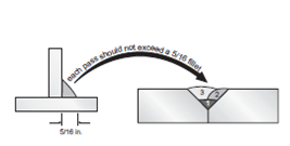
I use this illustration from the "AWS Manual for the certification for welding supervisors"

This is how big your single pass GMAW welds can be lads... No more than this.

This is what your stringer can fill... If you wiggle your gun to make this happen I don't care... If you wiggle your gun and make bigger welds you are out of compliance with our written shop standards and have pissed off the guy that can hurt you.

.
Parent - By ssbn727 (*****) Date 09-24-2014 22:46
Hey Larry,

Do those who work for you know what you're saying to them through an interpreter? If not, then I suggest that get a hold of your buddy there in Monterrey, or else that crew will just look @ you and say to themselves "Que? What is this crazy Gringo saying?" in Mexican of course...:eek::twisted::yell::lol::grin::wink::cool:
I know, you write everything down on paper and have it translated right?:grin::lol::yell::twisted::wink::cool:

Respectfully,
Henry
Parent - - By pipewelder_1999 (****) Date 09-26-2014 23:53
Tell me more about WHY this is true ? I have not seen the CM for welding supervisors but I have made quite a few welds on various structures with groove welds with individual passes larger than a 5/16" fillet weld equivalent size. Many of said structures and vessels still in service.

And again, I may be missing something in the context of this conversation. Just wondering if another welding wives tail is going to start from the highly peer reviewed reference you mention. Again, I understand company requirements, heat input blah, blah.. but does that book really say that ?

Gerald
Parent - - By welderbrent (*****) Date 09-27-2014 01:51 Edited 09-27-2014 01:56
Now, I'm with Gerald.  I always want to know the 'why' of a statement especially in a teaching like this.

I know that that manual and the course is designed for productivity, economics, etc.  There may be circumstances where that is very valid when it comes to heat input controls on special materials and/or applications.  And, it is noted you are talking about a wire application by GMAW only. 

But what is the justification for putting it into your company policies for any/all work being done?  Give me good science to support that especially since none of the codes I work to make such a call.  And, just because you do it, that doesn't make it LAW for everyone else regardless of YOUR justification. 

Granted, a 5/16" fillet weld will have a face width slightly larger than 7/16" so figure about 1/2" wide on your groove weld face before you have to break it up and do it in two instead.  AND, that is not a BAD size weld to place a limit at. (This is about what I like to weld at, let me play devil's advocate especially as a TPI who has to have facts and codes to base a call on not opinions regardless of who they come from).

But give us some facts as to who, what, when, where, WHY, and HOW they came up with that and supported it with enough intelligent facts that you incorporated it into your company policies.

Don't take this wrong Lawrence.  There is a teaching moment here with honest questions desiring constructive, intelligent, science driven, factual answers.  Don't let us down.  Just because some book promoted by AWS that someone else pawned off as an ultimate authority says it should be thus doesn't make it 100% true and supportable.  And is it based upon economics and productivity or out of quality and safety? 

He Is In Control, Have a Great Day,  Brent
Parent - - By Lawrence (*****) Date 09-27-2014 02:41
I may get back to this next week but;  why should I do your research for you?

You are a peer sir... Review it yourself :)
Parent - By ssbn727 (*****) Date 09-27-2014 06:27
In other words, they want empirical proof to justify the rule. From my observation, there are some important details, reasoning and of course - logic that's being omitted, overlooked or not even being considered yet in this interesting discussion IMHO.

Respectfully,
Henry
Parent - By pipewelder_1999 (****) Date 09-27-2014 13:32
I'll have to find one of them and check it out. There may be tons of stuff I have been missing out on. :).  I'm excited.
Parent - - By ssbn727 (*****) Date 09-27-2014 21:33 Edited 09-27-2014 21:39
What get's me Larry is not so much the actual size limitation per se although, it would nice to see where in the codes or standards (Possibly in one of the commentaries?) does the location of this rule presumably being based on empirical proof shown or, at the very least written as being mandatory as opposed to a recommendation, suggestion, guideline...

Finally, that illustration has some technical issues that should made aware of to whoever made the drawing...I'll attempt to write an in depth description of the illustration in question as detailed as I can possibly do so... While I do understand the premise of using that illustration to convey your intent Lawrence... I have to disagree with the choice of illustration to use as a visual aid to show your welders, and to whoever else sees it just how big their single pass GMAW welds can be according to your shop standard...

1.) The arrow originating from the "T" joint, and pointing @ the cover layer of the single "V" Groove butt joint has some words written above it stating this:

"each pass should not exceed a 5/16 fillet" Now that may look initially acceptable if one just glances @ the tiny words shown but, a person like myself will catch the ambiguity of that simple sentence and understand that the statement above the arrow in the illustration is technically confusing to say the least... Why do I notice and think that? Because I asked myself this:"How can it be written that each pass of a 5/16th of an inch leg size fillet can be immediately transferred and measured as a 5/16th" leg size fillet weld when once it's deposited into the weld groove of a single "V" groove one sided butt joint then technically speaking, it's no longer a 5/16th leg size fillet weld pass!"

2.) Based on the observation above, I decided to look into this further for the purpose of clarification and I came up with this: First off, we know that the dimensions of a fillet weld are not the same as found when measuring the size of a groove weld... Similar yes, but not the same, and this can be easily verified in AWS A3.0 unless a major revision of the associated definitions have occurred without my knowledge of such a profound change...

3.) So I compared the 2 different weld ed joints and how the parts and dimensions that make up each weld(s) are measured and this is what I observed:

A.) A 5/16th" fillet is generally understood as being a fillet weld with a leg size dimension of 5/16th of an inch or 0.313" (Rounded off from 0.3125"), equivalent to 7.9375mm...
Defined in A3.0 as a "Fillet Weld Size: For Equal leg fillets, the leg lengths of the largest isosceles right triangle that can be inscribed within the fillet weld cross section. For unequal leg fillet welds, the leg lengths of the largest right triangle that can be inscribed within the fillet weld cross section. See Figures 25 (A)-(E)"...

B.) The single V groove weld size is based on different parts to be measured and dimensions... Again going back into AWS A3.0... "Groove weld size" is defined as: "The joint penetration of a groove weld." I looked specifically @ Figure 26(b) and, it shows a description of what the groove weld size consists of, and how it is to be measured and dimensioned... Figure 26b shows the term "Joint Penetration or Groove Weld Size" dimension, and is measured starting from the surface of the joint with the opening of the V groove, minus the weld reinforcement to end @ the furthest depth of root penetration within the joint thickness... Or, (AWS 3.0) "The distance the weld metal extends into the joint root." (It should be written instead as:"The distance the weld metal minus weld reinforcement, extends into the joint root") See Figure 26...

C.) I then revisited the illustration Lawrence posted with an arrow originating from the "T" joint, just above the weld face of the "5/16th" fillet weld leg size" shown dimensioned @ the bottom of the flat member of the "T" joint, and reaching out with a curved arrow line across the distance between the T joint, and the V groove butt joint to terminate with an arrow head pointing down towards a weld face of a completed fill or cover pass of the Single "V" groove butt joint... With a depth of bevel approximately 2/3 the thickness of the joint showing in the cross section view of 3 groove weld passes that fill the "V" and, detailing in numerical order the sequence of filling the groove by numbering each pass... Written on top of that same arrow line is this sentence: "each pass should not exceed a 5/16 fillet".

So far I described an illustration representing 2 different types of joints and 2 separately dimensioned weld joint types, one being a T joint with a single pass fillet weld on one side, and another being a butt joint with a single V groove joint design on 1 side only with a depth of bevel 2/3 the thickness of each member, filled with multiple weld passes of groove welds and the other side left alone... Everybody agree with what I just described? Are ther clearly visible differences between the two joint dimensions? I know I do.

Like I said in the beginning that I understood the premise and intent of what you're attempting to convey Lawrence... I get that... I just don't agree that the drawing clearly  shows that the fillet weld size is equal to the groove weld size based on how the dimensions between the two are supposed to be measured according to AWS A3.0... Now if you meant that a groove weld face dimension should be equal to the shop standard fillet weld leg size then it should be clearly noted and dimensioned in order to avoid any confusion.:smile::cool:

Respectfully,
Henry
Parent - - By welderbrent (*****) Date 09-28-2014 00:09
Basically, for myself and I believe a re-wording of what you are saying Henry, is that the volume of the two will be very different even if the surface of the face is identical as the depth will not be the same due to the joint configuration.  The groove weld would have less volume because if it is the same width but not as 'deep' as measured by throat or 'leg'.  As such, how can one honestly compare the two as the drawing supplied by Lawrence indicates.  Why would one be a basis for limiting the size of the other.

Someone is comparing apples with oranges.

As Henry points out, there are other considerations with the basic idea as presented let alone with the science of it. 

He Is In Control, Have a Great Day,  Brent
Parent - By ssbn727 (*****) Date 09-28-2014 06:23 Edited 09-28-2014 06:39
My question now is this: How come nobody noticed this earlier? I know I did but, instead of reacting to it and immediately commenting, I decided to think about it first and perform the due diligence in research required so that I would have the empirical proof to challenge the notion that a 5/16" fillet weld size is equal in size to that of a 5/16" groove weld size...

I then decided to explain my long winded post by writing an in depth reply regarding  the illustration, by covering all of the details and citing my reasoning and logic so that there would be no doubt for anyone who read what I wrote - would understand what is going on in that illustration...

Comparing apples to oranges to say the least, is too simplified (even though I agree with you Brent) of an analogy to cover and convey exactly in detail what is being shown in the illustration and why the two weld types are not compatible to be considered as being equivalent in size dimensions with each other... Shop standard or no shop standard, and especially if the work is to AWS D1.1... Now I haven't read the Canadian equivalent to AWS 3.0 but, I suspect the logic is similar... Oh and btw, single layer thickness is specifically pertaining to what size dimensioned part of a groove weld? Joint penetration, one of the throats?

I'm being intentionally sarcastic in asking these questions because if you simply compare the parts of each of the weld types, the parts in a groove weld cannot be said to be equivalent to the fillet weld leg size dimension listed as such in the illustration... Not the thickness... You can't generalize a specific part of a particular weld type to be equivalent to a different weld type such as comparing the parts that make up a groove weld to the parts & dimensions found in a fillet weld if you're going to work to a code such as
AWS D1.1.

Respectfully,
Henry
Parent - - By Lawrence (*****) Date 09-29-2014 11:54
I think you guys are confusing a suggested "best practice" with a code limitation.

The original post mentioned what the "Company and QA wanted"    I happen to agree with the direction the OP's QA.

I think the discussion carried to this point mentions a number of good reasons to limit single pass weld sizes in production. 

Limiting weld sizes as mentioned in the excerpt I provided along with the term "should" makes a best practices statement that can be incorporated into detailed work instructions or a company quality manual that helps reduce the "risk" of defects due to larger sized deposits and overwelding, without disallowing code acceptable larger welds that will occur from time to time.

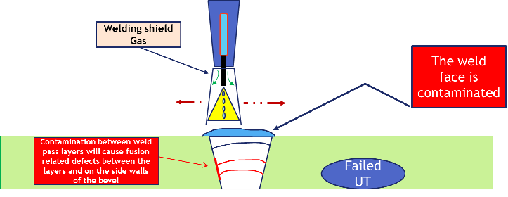
Can a larger deposit be made?     Yes absolutely.   My experience in the manufacturing area, specific with Spray GMAW tells me that fusion related defects (Failed UT in CJP connections) and overlap are common defects that find there source with excessive electrode manipulation by welders who want to fill large joints with fewer passes than are recommended in the CWS manual.

I will say this about "apples and oranges"    I think the following scenario explains how I employ this figure of weld volume.
.045 ER70S-6
400 ipm = about 290 amps with typical stickout
27 volts
Ar/C02 gas mix.

With the above spray transfer parameters a 5/16 fillet volume without whipping or weaving will occur at a travel speed of something like 12-15 IPM.   Traveling slower or weaving to increase fillet size or fill a groove opens the door for defects (think best practices not code).

Welders often "feel" like they are doing more if they make a single larger pass...  This is the notion I try to disabuse.  If the WFS remains the same the weld volume produced remains  the same with any given arc-on time.   The difference is quality of deposited weld.

I have seen more BEAUTIFUL wide weaved/whipped cap passes and fill passes fail UT than I can count.  Stringers are just more consistent.

The Original Poster asked for "information and recommendations"  I supplied both, in order to try to help him... Some from my own opinion based on experience related to burning 1.5 million lbs. of GMAW wire annually, some from the CWS manual, which I hold in high esteem.  

Nobody else has provided jack to the original poster... Just complaints about my input.
Parent - - By welderbrent (*****) Date 09-29-2014 17:01
Lawrence,

This is exactly what I did not want to happen.  I meant no offense in my desire to learn the science behind the opinion.  And, I did state that I myself prefer narrower beads but will not define that as absolutely NO weaving.  AND, I did not complain about your post.  Only asked for information.

Now, I agree, a good share of my direction is aimed more at the code requirements than just preferred methods.  And, the OP was more interested in methods.  That doesn't mean you can't help me with having science and more knowledge that would make it easier to explain to welders why it is best to narrow their weld passes as much as possible.

I appreciate your experience and knowledge and all the places you have worked that bring practical application to your input. 

So please, keep informing and still be the teacher.

He Is In Control, Have a Great Day,  Brent
Parent - - By Lawrence (*****) Date 09-29-2014 17:09
I'm not offended  :)

I just noted that there are a bunch of posts... But not much actual help given to the guy asking for it.

I'm pretty confident that there are others who do similar things who have not responded to the OP
Parent - By ssbn727 (*****) Date 09-29-2014 23:16
Grunt!:twisted::yell::lol::roll::wink::cool:

Oh but Larry, I did give the OP some guidance to answer his original query:

"-/- By ssbn727 (*****) Date 09-22-2014 22:08
Simple... Impose a shop standard that emphasizes your wishes and limitations then throw in discipline as a result of not conforming which is something you need to use @ your discretion as well as CYA ... Develop a training regimen if you want to before you implement the disciplinary aspect then throw down the hammer!:twisted::yell::lol::yell::roll::wink:

Make sure the changes you impose are passed along to the other departments, and written into your quality manual... 17 - 13 Chicago @ halftime. Gotta go!

Respectfully,
Henry"

Maybe you're referring to somebody else? Hmmmmm... Fascinating indeed! Btw, I do like the second illustration as it relates to the why it's a not preferred to deposit wider than required weld passes, and it's interesting to note how that example better explains why there should be a limitation, and can be used to counter any push back from the welders by incorporating the 2nd illustration into the shop standard I suggested earlier... That image is so much better to justify than your 1st illustration... Oh well, better late than never! 

Respectfully,
Henry
Parent - - By pipewelder_1999 (****) Date 09-28-2014 01:18
Is it possible that this "idea" is taken from the prequalified procedure limitations of D1.1 ? My 2010 is at the office but the single pass layer thickness I am pretty sure is limited to 1/4" (Slightly over the distance for theoretical face to root of 5/16" fillet weld).

However as a procedure variable outside the scope of D1.1 prequalified, no such requirement exists that I am aware of (And that does not mean it does not exist) But in my limited experience that is not where limits exist for many other codes.  Is that a good idea YES IT IS. I firmly believe that one of the leading causes of fusion related discontinuities is the thickness of the puddle and where the arc falls in that puddle.

I understand the requirement in that context. I just do not understand a "blanket statement" based upon the text you reference.  The 1st "Welding Supervisor" that brings that one to my attention as a criteria for rejection will definitely be queried as to a "REAL" acceptance criteria that binds that requirement. If he/she refers to the CMWS then I will probably follow up with something more in tune with the actual requirements related to the project.

There are just SO MANY welding wives tales that get generated from valid requirements that apply to a particular situation, Those requirements then become accepted as facts and many never question  the context of when they apply. Who is to doubt the word of a "Certified" person. Thinks  that happen in D1.1 Preq don't apply to qualified which don't apply to sec IX blah, blah blah.

Again, shop requirements, individual company requirements are those of the shop or company. Good/Bad or otherwise, they are what they are. Actual acceptance criteria is what it is. Neither one by itself make for a quality program.

Have a good day.

Gerald

ALSO, I ran into some of your HR people at a recent conference, they spoke very highly of you. I told them what I thought about you based on what I've seen here.
Parent - By ssbn727 (*****) Date 09-28-2014 05:58
Blah, blah, blah:smile::grin::lol::yell::twisted::yell::lol::yell::twisted::yell::lol::yell::lol::yell::lol::roll::roll::roll::wink::cool:
- - By 803056 (*****) Date 09-19-2014 14:28 Edited 09-19-2014 15:11
Lawrence; show me a 5/16 inch fillet weld deposited with 0.045 inch diameter wire, with no weave, with a 10 degree push angle on 1/2 inch plate, that has fusion to root, in the horizontal or overhead test positions, and meets AWS profile requirements; and I'll buy you dinner at FabTech.

Henry makes a good point, so let's stay with semiautomatic, no mechanized or automatic samples (but I still would be interested in seeing the latter as well). And let's stay with low carbon or low alloy steel. No special tricks, just a standard everyday production weld.

Al
Parent - - By ssbn727 (*****) Date 09-19-2014 14:53
Well Lar? Are you game? now there needs to be some clarification here Al... why? Because I don't recall reading in your challenge that you are referring to a manually deposited weld as opposed to an automated weld instead and that's why it is important enough to bring up... This ought to be interesting enough to monitor.:grin::wink::cool:

Respectfully,
Henry
Parent - By CLH1978 (**) Date 09-19-2014 15:01
In our area of the Midwest, M5 is 95% argon and 5% oxygen.
Parent - By 803056 (*****) Date 09-19-2014 15:10
Good points Henry. I revised and incorporated the conditions into the challenge.

Al
Parent - - By Lawrence (*****) Date 09-19-2014 15:56
Horizontal
Parent - - By Lawrence (*****) Date 09-19-2014 16:08
Sidebar:

This clearly illustrates why I prefer the penetration profile of the Argon/Co2 gas mixes.

I rant from time to time about my distaste for Ar/Oxy mixes, especially mixes exceeding 2%

If Johnny tilts the gun just another hair on that 95/5 he will miss the root, but it won't be seen with a visual examination.
Parent - - By 803056 (*****) Date 09-19-2014 16:53 Edited 09-19-2014 16:55
GMAW or FCAW?

Single pass?

No side to side oscillation?

What are the measured leg and throat sizes?

Boiled or baked?

Al
Parent - - By Lawrence (*****) Date 09-19-2014 17:01
Solid wire

Single pass... You see the macro

5/16 legs... Just a fillet gage... The triangle is obvious so I'll let you do the math for the throat :)

Baked....... and a bucket of lemon butter.

If it were FCAW it would be 10-20 degrees drag...  And I could make it 3/8" without trouble.   But I don't have the macros to back that boast :)
Parent - - By ssbn727 (*****) Date 09-19-2014 19:22 Edited 09-19-2014 19:28
What plate thickness did you use? When I ask this, I mean the actual measured thickness and not the nominal thickness... Was it 3/8ths of an inch? Do you have another view of these t-joints besides the macro being shown?

Respectfully,
Henry
Parent - By Lawrence (*****) Date 09-19-2014 20:25
Good Lord Henry !

Zip it man.

You are ruining my Lobster
Parent - By pipewelder_1999 (****) Date 09-26-2014 23:43
If those were pushed then I should send you a Lobster too. Maybe just a few Tenn Mudbugs. I don't doubt you are telling me the truth but I have fought this on MANY welder tests that continued to fail.

Of course I may be completely lost as I received a poster from the blue company a week or two ago that says amperage goes down as wire feed speed goes up. So I am throwing my knowledge out the window.

Gerald
- - By 803056 (*****) Date 09-19-2014 20:19
Nice looking cross sections. Now let's see a few your welders are producing on the shop floor.

I'll bring the lobster with me. We can mircrowave t in my hotel room. MMM, good!!

I'll see you at the show and we can grab inner one evening. We'll finalize when we're closer to FabTech.

Best regards - Al
Parent - - By Lawrence (*****) Date 09-19-2014 20:24 Edited 09-19-2014 20:28
I said Baked Al.

Bring your rod oven :)

You can modify FC2002
"All baked potatoes in the rod ovens shall be held at a min of 250F for a
period of no less than 4 hours, .....or until a fork is easily inserted to confirm
that they are completely done."
Parent - By ssbn727 (*****) Date 09-19-2014 20:57
I hope you don't bake your lobster for four hours too!:lol::yell::twisted::yell::lol::twisted::yell::lol::yell::twisted::yell::lol::grin::smile::roll::eek::wink::cool:

Btw, I'm verifying Lar! To me it's "No measurement to compare - no pass ticket for lobster!":eek::roll::eek::surprised::roll::eek::roll::twisted::yell::lol::yell::lol::grin::smile::wink: 
Enjoy your "Crustacean" Lawrence!:lol::yell::twisted::yell::lol::yell::eek::roll::wink::cool:

Respectfully,
Henry
Up Topic Welding Industry / General Welding Discussion / manipulating welds

Powered by mwForum 2.29.2 © 1999-2013 Markus Wichitill