 By 803056
  Date
Date 06-06-2015 15:31
Edited 06-06-2015 17:12
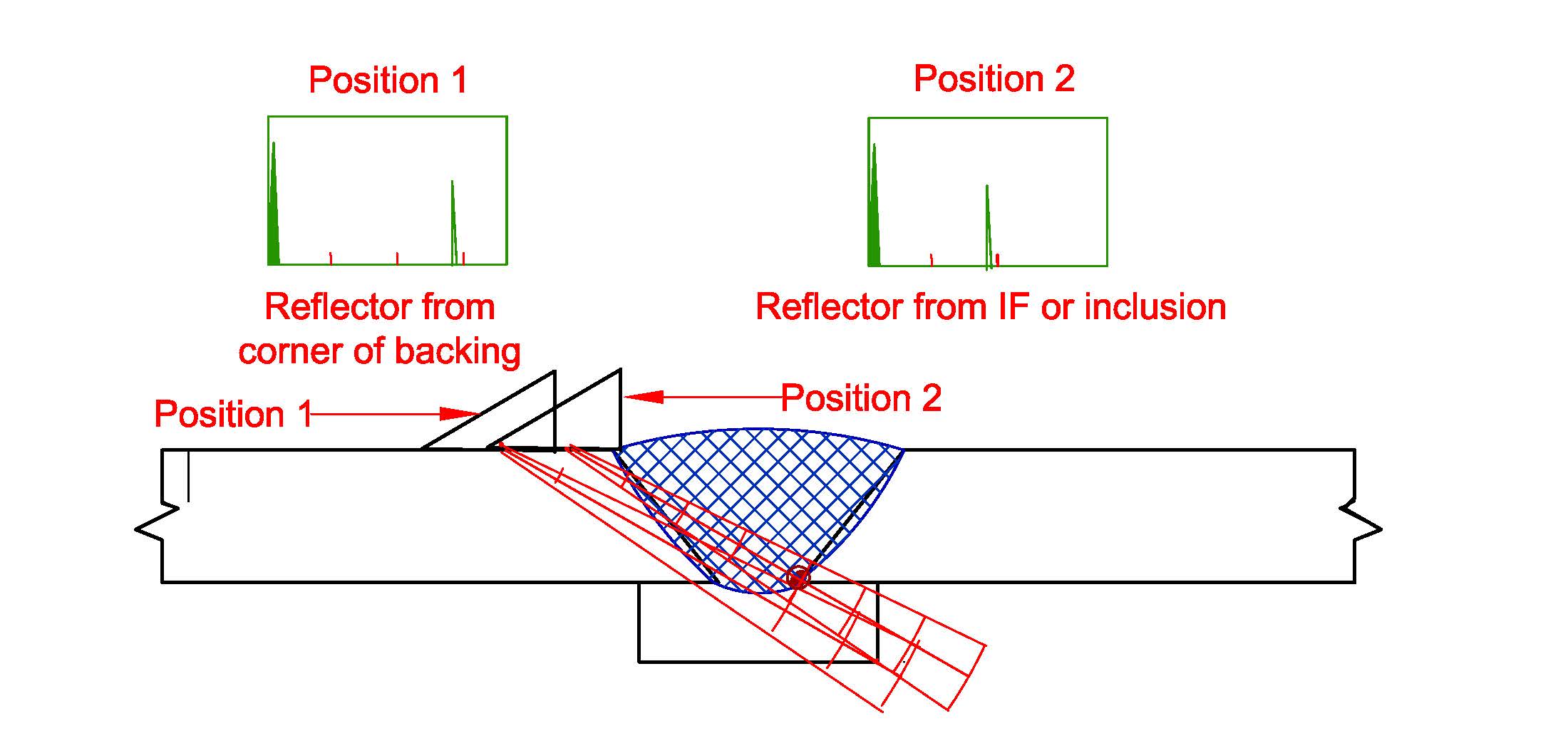
I would be concern the UT tech is misinterpreting the display. If he/she plots the sound path carefully, it may be discovered the signal on the display is due to the sound beam passing through the root opening into the backing and back to the transducer.
Moving the transducer back and forth may allow the technician to determine if the signal displayed is a defect in the root or the backing (see attached sketch). A change in sound path should allow the technician differentiate between the defect and the backing. If there is still a problem, a change in the transducer angle may help. At a shallow angle (70 degrees), the signal may not be able to bounce off the backing and back to the transducer (no reflector displayed). A defect, if it is an inclusion, should produce a signal regardless of the transducer angle. The sound path distance will change due to the different angle, but they should plot the same depth (trig functions).
If the technician is rejecting welded joints after welded joint, all with the same sound path distance, I would suggest a different transducer angle as a check. The defect will still be detected in most cases, unless it is a planer oriented parallel with the sound beam. However, the reflector from the backing may well disappear altogether with the change in transducer angle.
Al


