Not logged inAmerican Welding Society Forum
Forum AWS Website Help Search Login
Up Topic Welding Industry / Technical Discussions / Welding of high tensile steel
- - By cudaxtreme (*) Date 07-31-2007 05:06
Hi,

I have a particular disturbing problem welding high tensile steel.  The base metal is StE890(5mm) welded to weldox 900(5mm).  Both have similar yield strength at 890~900 MPa and tensile at >940MPa.  The filler used is Fluxofil 45 which is a gas shielded basic flux cored wire.  The gas used were 80%Ar 20%CO2.  Welding parameters were 28-30V, 200-250A, travel ~200mm/min.

I have tried preheating to 100C, post heat, slowed cooling but will always show discontinuity at face bend fusion zone.  Root bend have no problems.

Mechanical properties as welded were tested as below
Tensile 985MPa, broke at StE890
Hardness base metal (weldox 900) ~335HV
Hardness HAZ (weldox 900 to weld metal) 300-389HV
Hardness weld metal ~385HV
Hardness HAZ (weld metal to StE890) 280~393HV
Hardness base metal (StE890) ~315HV

This is meant for welding of crane boom.  Our crane contractor have problems qualifying the PQR.  All manufacturer recommended parameters were followed, apparently no mention of preheat/post weld heat treatment, interpass temperature.

My guess is that the high hardness might be causing the face bend to fail but it met the required tensile and yield strength. I'm running out of ideas how to get this going.  Please kindly advice. Thanks!
Parent - By js55 (*****) Date 07-31-2007 13:42
Let me preface by saying that I know nothing of the alloys you are dealing with, but given certain generalities about high strength alloys maybe I can offer something. I would certainy defer to someone who knows these alloys specifically.
First of all you mentioned nothing of PWHT, even though you did say post heat. Is this a PWHT?
Second, sometimes when roots bend and faces don't its because, to a certain extent, of additional stress relief from subsequent beads. You may need to consider a temper bead process with removal of the final cap. Also, what is the strengthening mechanism of this alloy. High carbon martensite? Microalloy precipitations? What?
And it seems to me your Vickers is hittin carbides in the HAZ as well (the 390's). Carbides that are harder than the UBM where some of the carbon is still in solid solution.
And in general high preheats, high interpass temps (though you may need an interpass max as well if you want to interpass temper the martensite), maybe even a bakeout, and a PWHT.
Parent - By G.S.Crisi (****) Date 07-31-2007 19:09
Have you considered applying Vibrational Stress Relief (VSR) instead of PWHT?
Crane booms can be considered as being a structural steel construction, for which VSR is particularly indicated.
Giovanni S. Crisi
Sao Paulo - Brazil
Parent - - By 803056 (*****) Date 08-01-2007 02:59
I would expect the tensiles to be on the high side if insufficent preheat or post weld heat treatment was not utilized. Now the bends; the bend radius is a function of the tensile strength, ductility, and thickness of the test piece.

A standard bend mandrel of 1 1/2 inches diameter produces a 20% elongation if the sample is 3/8 inch thick. If the 3/8 inch material only has an elongation of 15%, it is going to fail when stretched to 20%.  If the sample is thicker, the elongation is greater than 20% and it may well crack. If the material is thinner than 3/8 inch, the elongation is less than 20% and it may well pass even if a discontinuity is present, assuming all other parmeters are held constant.

I suggest reviewing  AWS B2.1 for the requirements of the bending mandrel base on the mechanical properties of the base metal you are working with.

Best regards - Al
Parent - By js55 (*****) Date 08-01-2007 13:30
Al,
Don't forget he mentioned that the root bends passed, the face bends failed. Though, as you mentioned, it could be that the root bends were thinner.
Parent - - By cudaxtreme (*) Date 08-02-2007 04:32
The bend diameter is 38mm. Weldox 900 have a min 12% elongation.  In accordance to ASME IX, the diameter should be 36mm.

Today I tried welding a high heat input temper bead on top of the existing cover pass.  The temper bead is then grinded off but I'm still getting openings at the fusion zone.

I tried bending the both base metal weldox 900 and StE890 produces no defect.
Parent - - By Kix (****) Date 08-02-2007 15:31
Whats the wire classification you are useing?  What parameters are you running at also for your fill and cap passes?  Could very well be a case of bad parameters that are causeing lack of fusion in the sides of the bevel.
  Weldox 900 has a carbon equivalent ov CEV (llW)* 0.56 ,  recomended interpass temp of 150-175 deg celsius,  Recomended preheat of 75 deg celsius.  For weldox 900 it is also recomended to undermatch the steels tensile with a lower tensile filler.
Parent - - By js55 (*****) Date 08-02-2007 15:54
Whatever is happening is different in the 'top' half of the weldment than on the 'bottom' half. Obviously with root bends the root is in tension, the cap is in compression, and vice versa, with a neutral axis at mid thickness. In this case the cap is opening up in tension (with 20% elongation at the surface) and there seems to be no manifestation in either compression or root tension.
As kix mentioned perhaps there is a performance difficulty or WPS difficulty when laying down the upper layers causing a fusion problem. Or there may be something metallurgical. There will be an unmixed zone at the fusion line. 
Parent - - By js55 (*****) Date 08-02-2007 15:57
And, as Al indicated, perhaps your cap is performing as it should, failing at 20% when 12% is all that it is required to have, and your root is somehow out performing the 12% min.
There is provision in the code for materials that will not achieve a 20% elongation.
Parent - - By js55 (*****) Date 08-02-2007 16:15
Another thought: what is the anticipated or minimum ductility or yield strength of your filler?
You may consider longitudinal bends as opposed to transverse. This is common when properties of fillers are radically different than properties of base metals. Used commonly with dissimilars. The thing is, if the ductility of the filler is greater, or the yield strength much lower, than the ductility or yield of the base metal to an extreme, then your fusion zone will take a much greater strain than 20% as the filler gives and the BM doesn't. That is the very reason for longitudinal bends.
If this is the case you should be able to see a sharp bend at the fusion zone(usually). Sometimes its subtle and difficult to see but almost always visible if you know what your looking at.
Parent - - By Stephan (***) Date 08-02-2007 18:38
Jeff,
Gentlemen,

firstly I would like to state it explicitly:

I honestly have no personal practical experience in welding such as high tensile strength steels.

Now you might think, what the heck does he want then again? And perhaps you are right and I should better remain silently and observe your discussions on this topic devotional. But allow to say, that this what you all are talking about here is a very interesting - since practical - matter.

And... as you - Jeff - kindly stated in another post (quote): "...hey, we learn something everyday!"

Please know, that I am one of a few persons within the German Welding Society who are having a stringent interest to pursue a reevaluation of terms being used in direct coherence with "heat input" - "energy input" - "thermal energy input"... in particular in combining new or sophisticated welding processes + sophisticated materials. Those people think that this mentioned combination needs new elementary considerations, since the materials are produced by combining metallurgical and thermomechanical measures, their wall thickness is strongly decreased and new processes (e.g. Hybrid-Processes etc.) are sometimes difficult to calculate with regard to their thermal efficiency values.

Due to I have had lots of interesting discussions on this target in the past few months or meanwhile years, respectively.

I have quiet good contacts to some engineers coming from the steel manufacturers side (THYSSEN KRUPP STEEL - TKS).

In the coherence with the efforts running in the field of reevaluation I once had the chance to be part of a discussion with one of the most well-known German engineering experts (one of the "Great" ones) - Mr. Peter Gerster - in the field of High- and Ultra High Strength Steel Welding (in particular crane building and construction).

When we disucssed the influence of "heat input" on the mechanical peoperties of welded High- and Ultra High Strength Steels, he smiled and stated (translated):

"Ladies and Gentlemen, for achieving proper and sound welding joints on these materials I don't need any "heat input" calculated by the well-known formula(e). The only thing I need to obtaining a sound welding joint as well for the most advanced steel grades (> 1200(!) MPa Tensile Strength) is the knowledge of the C-Equivalent of both base- and filler material and - as the crucial point - the t8/5 time!" Hereby I can estimate if the later welded material may make any kind of problems within the joining zone."

Well I do not know if he was right - although he is really well-known as an outstanding expert in this field - but as a result of this statement I asked my contact person at TKS if they - as the steel mill producing those materials - have any special programs for calculating perhaps the C eq and t8/5 time, respectively, for their manufactured steel grades.

And the answer was "Yes!".

He has sent me a CD-ROM at that time containing extraordinary helpful theoretical as also practical information in regard to welding these steels. And additionally a calculation program which makes it possible by inscribing the alloy element values etc. for being able to calculate different things like "C Equivalents", "Preheat-Temperature", "Heat Input" and the "t8/5 time".

Well, due to my initial statement I may be definitely wrong but, when I read the welding parameters "cu-da-xtreme" has stated and in particular the welding speed of 200 mm/min (= 3.33 mm/second) in combination with the base materials wall thickness (2-dimensional heat conduction), I do not know if perhaps the t8/5 time (basing on the statement of Peter Gerster) may be an aspect to be "viewed" a bit closer. If it would be possible anyway to pass on to you the program coming from the Thyssen Krupp Steel CD-ROM you could calculate by using the chemical composition of base- and filler material the usable t8/5 time to control if the heat input by using the mentioned parameters in combination with the welding speed yield the "correct" range for the steels to be welded.

Only a thought...

Best regards to you all,
Stephan
Parent - - By js55 (*****) Date 08-02-2007 19:20
Stephen,
What bothers me most about this as described is the face bend isolated nature of it and the fusion zone nature of it. This has a tendency to tell me we are dealing with something more specific than heat input, C-eq, or delta 8/5. Having said that, who knows. As I've stated before in other threads, its much easier to post our thoughts and wax hypothetical than it is to actually be under the delivery gun and have to come up with a solution yesterday. Leave no stone unturned and best guess.
Parent - By Stephan (***) Date 08-02-2007 20:17
Jeff,

I agree!

Hoping to have the luck to coming to know the problems solution...

Best,
Stephan
Parent - By 803056 (*****) Date 08-02-2007 23:11
Armchair analysis is more difficult than it appears to be.

There are many things that we don't know and can't see from our vantage point.  We only know what we are told by the person posting the inquiry.

I have had face bend failures in carbon steel when the top weld layer extended "way" past the edge of the prepared groove. The weld bead extending over the edge of the groove (on the base metal) is very thin once the weld is ground flush. It is at the edge of the toe that the weld pulls away from the basemetal with a planar fracture under the weld even though there appears to be sufficient fusion, i.e, there is no visual evidence of incomplete fusion or other discontinuity.

I attribute the failure to the differences in mechanical properties (ductility I would imagine) of the weld and base metal. The fractures appear to be the result of shear stresses rather than a crack due to tensile stresses "stacking up" around a discontinuity in the weld.

Not seeing the ruptured surface in this case makes any conclusions on our part pure conjecture. But it is fun to discuss these problems even if there is no clear cut solution to the problem.

Best regards - Al
Parent - - By GRoberts (***) Date 08-02-2007 23:01
What kind of bending machine are you using- plunger style or wrap-around?  If plunger style, is the radius of the bends smooth after bending, or is it non-uniform.  If it is not smooth, try a wrap-around bending machine.  They deal with the dissimilar strenght material much better than plunger style as they can elimintate kinking.  It has similar benifits to longitudinal bends if you can access the right equipment.  A Mal-adjusted wrap-around bender (ie. too big of a gap between the roller and the specimen) can produce poor results as well though.
Parent - - By cudaxtreme (*) Date 08-03-2007 01:09 Edited 08-03-2007 01:34
Here's more info on weldox 900 and the wire

Weldox 900 - grain-refined

C - Max 0.2%
Si - Max 0.5%
Mn - Max 1.6%
P - Max 0.02%
S - Max 0.01%
B - Max 0.005%
Nb - Max 0.04%
Cr - Max 0.7%
V - Max 0.06
Cu - Max 0.1%
Ti - Max 0.04%
Al - Max 0.018%
Mo - Max 0.7%
Ni - Max 0.1%
N - Max 0.015%

CEV ~ 0.55%

Fluxofil 45 - Oerlikon - nominal ferrite weld metal
Typical values

C - 0.07%
Mn - 2.0%
Si - 0.5%
S - 0.008%
P - 0.010%
Cr - 1.25%
Ni - 2.2%
Mo - 0.45%

YS - 980MPa
UTS - 1070MPa
Elongation - 15%
Charpy @ 20C - 55J

This particular wire have been tested by several competent welders and all failed at the face bend fusion zone.  We even switched machines, gases(from Ar-CO2 to CO2), different roll of wire.  The bend tests were intially done at a certified metallurgy lab using the plunger style, the test specimens were smooth and rounded.  After sending 2 plates and all 4 face bends failed at the fusion zone, we are now doing it in-house until we are certain that the problem is solved.
Parent - - By cudaxtreme (*) Date 08-03-2007 03:52
I had a interesting observation today.  The thermal coefficent of both base metal varies quite alot.

The temperature was taken 50mm off the weld joint just after welding.  The S890 measured ~180C whereas the Weldox900 measured ~270C.  Both plates are identical in size and thickness.
Parent - - By Stephan (***) Date 08-03-2007 09:35 Edited 08-03-2007 10:05
cudaxtreme,

this goes furthest towards what I said when I've spoken about "high advanced" steels.

I guess that these materials do need a very specific consideration - in particular in combination with sophisticated welding processes.

I have made some similar practical experiences when GMA Welding Retained Austenite (TRIP) Steels - not far as high in strength and wall thickness as in your application but however - although both steel grades were similar from their standardization and only were supplied by different steel manufacturers (two of the largest in Europe) and all the used welding parameters were used the same, we achieved very different welding results in regard to the mechanical properties and especially welding behaviour!

This - so we could find out at that time - does make a "generalized" treatment of those "new" materials twice as hard as ever before. And the best statements came that time from the steel mills themselves. They have confirmed more or less that there can occur such differences although the chemical composition does vary only within the fixed limits.

My guess is thus that they use different ways - at least in details - of thermomechanical treatment while milling the steels.

Although I do not know exactly. It's only a guess...

Edit: By the way, the more I am thinking about your observation and the very elaborated comments coming from the other appreciated colleagues, the more interesting I find is your problem - unfortunately it remains basically a problem.

Considering what Jeff said by treating the different properties between filler- and base material one could perhaps also find a possible coherence between the different properties of the HAZ between the both base materials induced through the different heat conduction properties of both materials. Therefore it would be interesting if there is a "preferred area" of failure when comparing both halves, seen from the centre of the welding seam.

But it may also be that I am thinking wrong by having a false imagination of the parts you have to weld (geometry etc.)...

Nonetheless best regards,
Stephan
Parent - - By Kix (****) Date 08-03-2007 18:16
Well, in my lil hardox-weldox booklet here it says to just use a basic low hydrogen flux electrode.  I have no idea what that Fluxofil 45 is. The fluxcore wire they are suggesting is just you basic AWS A5.29 E12XT-X and an AWS A5.5 E12018 for stick welding.  SAW is an AWS A5.23 F12AX-EX and for just plain old solid wire MIG is an ER120S-X.  I'm getting ready to do some testing with an E81T-1-Ni1mH4 wire on some weldox 500.  Hopefully the procedure qualifies without any probs.
Parent - - By Stephan (***) Date 08-03-2007 18:57 Edited 08-04-2007 08:56
Hey Ray,

only two or three sentences on the OERLIKON Fluxofil 45 FCW.

OERLIKON Fluxofil Flux Cored Wire(s) are really pretty fine (welded cross section) wire electrodes. We have used that time the Fluxofil 31 basic FCW which is a kind of a "legend" in Germany due to its capability to be used for restricted weldable high C-containing Carbon Steels.

Due to their closed - since welded - cross section they have very low (< 5ml/100g) hydrogen contents, comparable to what you have stated.

I had a short look onto the data sheet (in German language) of the Fluxofil 45 wire electrode.

OERLIKON recommends 82Ar/18CO2 shielding gas (M21 acc. EN 439) and is mentioning explicitly that the mechanical properties of the weld metal deposit are influenced by cooling rate or "heat input" and working temperature, respectively!

Just as an additional information...

Best Regards,
Stephan
Parent - - By Kix (****) Date 08-03-2007 19:51
I was under the impression that this type of steel had a low (CEV) and didn't really need to be welded with anything special.  The wire i'm using is a low hydrogen flux cored wire, but i do not know if you can get it in the 120,000 tensile range.  It's supposed to compare to an E8018 stick electrode. I've used some different wire from a few countries over that way and i was very impressed.  It allmost ran as good as the stuff we get over here. ;-)
Parent - - By Stephan (***) Date 08-04-2007 08:52
Thanks Kix!

I understand...
Parent - - By cudaxtreme (*) Date 08-06-2007 03:06
Some bend tests updates, looks like longitudinal bend is the way to go

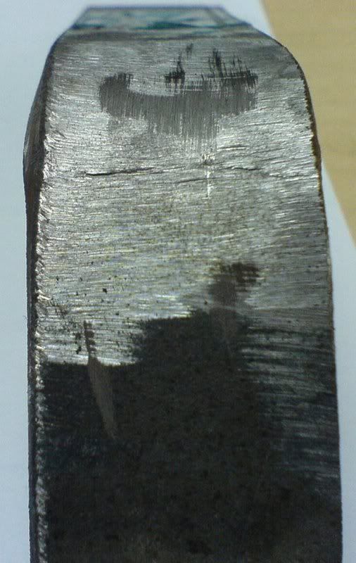
This is how it looks like when preheat = 100C and interpass between 200 - 300C

I did not even finish the bend as the discontinuity is very obvious

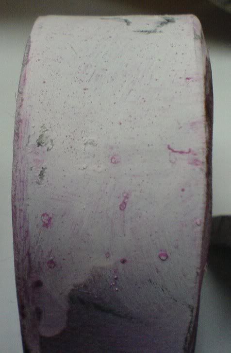
This is the transverse face bend when preheat = 100C and interpass < 150C

Discontinuity is ~3mm

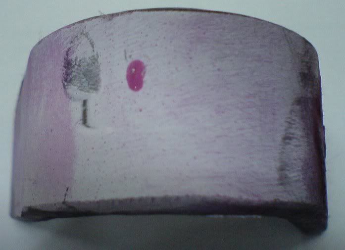
Another transverse face bend with preheat = 100C and interpass < 150C

Discontinuity is ~2mm

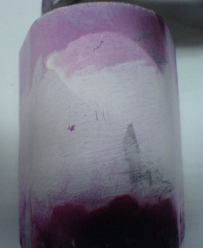
Longitudinal face bend with preheat = 100C and interpass < 150C

Discontinuity is ~1mm
Parent - - By 803056 (*****) Date 08-06-2007 04:43
Boy, I love this forum!

These photos provide an important clue to your problem.

Notice the marks left by your grinding operation. They run parallel to the axis of the weld. They act as stress risers when you perform the bend test! They may be a major part of your problem. It is preferable for the scratches from the grinding operation to be parallel to the length of the test piece.

In addition to the direction of the grind marks, consider using a longitudinal bend just to see if there is a difference in the test results. If your HAZ is much softer and more ductile than the weld or the unaffected base metal, the majority of the bending stress will be accommodated by the HAZ. We call it "church steepling". The longitudinal face and root bend will overcome the problem of a soft HAZ. 

Stephan, please forgive my ignorance, but what is this "t8/5" you refer to?

I'd rather learn than churn!

Best regards - Al
Parent - By Stephan (***) Date 08-06-2007 07:09
Al,

I once again agree 100% with what you've said.

I love this forum, too!

If you allow me to say, great points with respect to "stress raisers".

Well, today it's me who has to hurry to get on the road. Therefore with regard to the "t8/5" cooling time only two sentences briefly recalled from my brains "hard disc memory".

As far as I know the most important transformation sequences in cooling those materials (High Strength and Ultra High Strength Steels) after welding, in regard to their final microstructure, take place in the temperature range between 800°C and 500°C, or, as Jeff has called it, the delta between 8(00)/5(00). As far as I remember correctly within this range the thermodynamical "driving forces" acting on the Austenite are really "tough".

Due to it should be - as far as I remember - a quite sensitive effort to "balancing" both the hardness ("cold cracking") of mainly the materials heat affected zone and its mechanical behaviour (ductility etc. with regard to impact toughness) one should try to find more or less exactly that window of t8/5 cooling time which is a specific for the base material in combination with the used welding process, preheat temperature,... .

In relation to the materials composition (Ceq), its thickness (2- or 3-dimensional heat conduction behaviour), "heat input" (whatever it really may be) it is possible to practicable calculate the optimal cooling time between those two mentioned values.

As far as I have mentioned Thyssen Krupp Steel, for instance, as a High Strength Steel producer, has calculation programs basing on even those mentioned parameters for enabling the "correct" welding conditions etc.

I know, some of the other appreciated colleagues may certainly have better or more in-depth explanations, since it is - as usual - surely possible to describe more on this.

I have made a quick search on the www and surprisingly I have found a wonderful link, please see also:

http://homepage3.nifty.com/yurioka/exp.html

from NIPPON Steel.

This, as far as I have seen in all briefness, is truly comparable (of course it has to be :-) ) with the methods used by Thyssen Krupp Steel and which were contained on the CD-ROM of what I have spoken about!

By the way, Al, who am I to "forgive" you anything?

I don't want to be a bootlicker, but I honestly wish that I could ever gather just a thousandth of what your experience and knowlegde is!

My best regards to you,
Stephan
Parent - By DaveBoyer (*****) Date 08-07-2007 02:54
The direction of the grinding marks or "lay of the finish" as it is called out on drawings becomes more of an issue as ductility decreases. With a lot of ductility it is nearly a non issue, as hardness increases and ductility decreases You aproach a situation much like cutting a new window pane from a sheet of glass, score and break.
Up Topic Welding Industry / Technical Discussions / Welding of high tensile steel

Powered by mwForum 2.29.2 © 1999-2013 Markus Wichitill