Hey guy's. I have a job coming up where I have some 6 1/2" pipe coming out of the ground,vertical,(round),and I then have to lay on top of it some more 6.5" pipe and the guy wants it notched so it is similar to what you have on a roll cage. It is a non-critical job.It is solely to be used as a heavy duty railing in a parking lot so cars wont go through an office building.The cutting is the easy part for me,but,I am not sure of the way to notch it out so it fits pretty snug the first time..if ya know what i mean? I dont want to be out there floundering with that part of it .I have done these joints with tubing notchers ofcourse,but never anything of this dia. the wall thickness is .375 I dont need it to be an "exact" fit-up,but,since the uprights are already in the ground,I dont have much room for error.Any help much appriciated.Gary.
you say 6.5" dia pipe...i'm going to assume it's 6.5" outside diameter. if that's the case, just find a couple pieces of scrap 6" pipe and keep cutting until you get that perfect fit BEFORE you go out on the job. once you get it the way you want it you can get an old wraparound or a couple of those manila folders (tape 2 of them together so the edges are straight), wrap it around the fish-mouthed end and trace it with a pencil. cut along the line you just marked and BAM! (like Emeril) you have a template for all of your fish mouths!
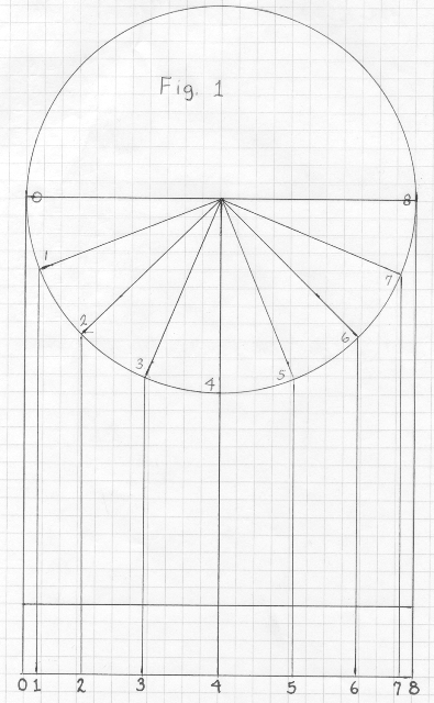
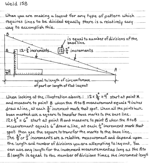
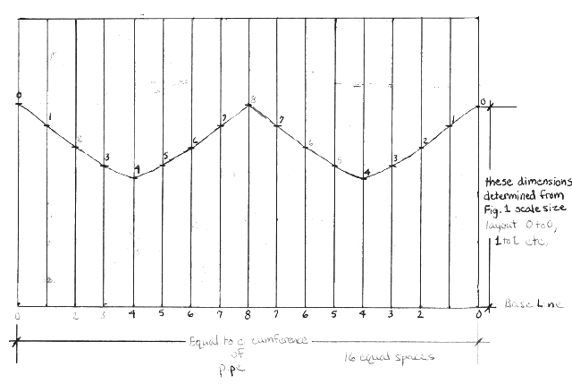
Hello Gary, I threw this together rather quickly but if you can make heads or tails of it, it might make things a bit easier for you. Fig. 1 needs to be a full size layout of the end diameter of the pipe and it needs to be divided into 16 equal sections, although only eight of them really need to be used, as I have drawn in the example(4 of the eight are identical to the other 4). You then need to draw a graph that has a base line that is equal to the length of the circumference of the pipe you are making the pattern for and is divided into 16 equal parts, the second page that I have included can help to divide that up equally. Next, use the information from Fig. 1 to mark off the lengths onto the graph that you have drawn. The example that I have included is definitely not a scale rendition of anything but should give you the general idea. When you have the pattern completed you can wrap this pattern around the post that you have and cut the necessary saddles to accept your top pipe rail. By using the number 0 line position from the the pattern you can orient all of your cuts in a proper line. Best regards, Allan
do you fold this page at any time,im confused.i understand the sections but how do you get to fiqure 3
Wow.Thanks again for AWS message board coming through.I knew there was some formula but couldnt find it on the search engines.I like the way there are so many different ideas on this website.From dead-rekoning get-er-done,to technical approaches.I will try to digest the diagrams and give it a shot.I may also do the" tweak a piece till it fits" method if I have the time.Anyone else have any tricks?? Again thanks.I'm now not as stressed.:)
LEE as in the wrap-a-round mfg co. makes a set of templates you can buy at a well stocked welding supply store. They are nice and thick and will last a long time, downside is, though you have to buy the set. You do know the adding machine tape method of dividing pipe into 1/4s, 1/8s, 1/16s etc???Email me your ph. # if not, as these are easier to verbalize than the much confusing written instructions.
Hello 52lincoln, the figure 3 that is included in my post would be cut out and wrapped around the outside of the pipe end, the two zero points(the two ends of the pattern) would meet as you wrapped this around. You would then trace a line along the top edge of this pattern to follow when you cut out the pipe end to accept the horizontal pipe. The finished cut would have two peaks and two saddles to accept the horizontal top pipe rail. Hope this makes sense. The actual pattern would not have the sharp points or sharp-shaped troughs that are shown in the example that I included, I got into a bit of a rush and didn't make a scale pattern for this example. Best regards, Allan
i sent you a private message check your box
Ok.Found a *****en site for this. Go to metalgeek.com and look up "tube coping calculator".I just printed out a pdf drawing---cut it out--taped the two pcs together--then traced it on to two taped-together manilla folders---cut it out-- and viola, I rolled it up until the two ends met--measured the diameter and it was 6.5". It formats the pdf to scale according to the size pipe/tube dimensions you enter so you dont even have to convert at all.COOL>:):):) Got all your messages and thank you all.Check out that site.What Aevald was showing us is what is called " parallel line development". I saw it on a site for formulas and he was spot-on as to this being the way to arive at it mathmaticaly.Gary.

 Forum
Forum


