Not logged inAmerican Welding Society Forum
Forum AWS Website Help Search Login
Up Topic Welding Industry / Technical Discussions / ISO WELD SYMBOL INTERPRETATION
- - By 100perpen (*) Date 05-20-2008 12:59
We have a sub assembly with ISO weld symbol callouts. I will try to post an image of the symbol in the hope the group could help with it's interpretation.
The image should follow shortly.
Parent - - By 100perpen (*) Date 05-20-2008 13:40 Edited 05-20-2008 13:52
I'm having some difficulty posting the image. I will keep trying.


I added the pic for you--JW
Attachment: PicforJohnRichter.bmp (304k)
Parent - - By jwright650 (*****) Date 05-20-2008 13:48 Edited 05-20-2008 14:01
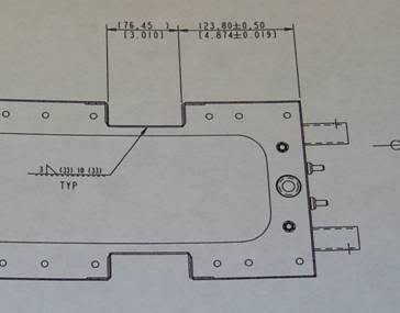
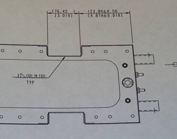
It looks like an intermittent fillet weld on the otherside, but I can't make out the pitch due to the pic being too small.
Parent - - By 100perpen (*) Date 05-20-2008 14:01
On the reference line it has  3 then fillet then (33) 10 (33)
Parent - - By jwright650 (*****) Date 05-20-2008 14:06
My *guess* is:

Place a 1/8" fillet weld on the otherside for 1 5/16" length, skip 3/8", add another 1 5/16" length weld to make up the total 3".....
Parent - - By 100perpen (*) Date 05-20-2008 15:02
Thank you John.
You have helped answer many questions here.
We still have ??? with..... Is this a NEARSIDE call out per ISO and is the 3/8" skip "end to start" or on "weld center???
Parent - - By jwright650 (*****) Date 05-20-2008 15:32
Mind you that is only my guess. I was really hoping someone with ISO experience would chime in and either agree or disagree with my guess. Sometimes, I think a picture with hatched in weld to acutally depict where the weld is to be deposited is a good thing when it is unclear about exactly what is intended.

I'm curious why you are asking about the "nearside" because the fillet symbol is on the "otherside" of the reference line....

....my guess on the intermittent weld is (weld)skip(weld) actual weld length dimns rather than weld centers....
Parent - - By 100perpen (*) Date 05-20-2008 17:53
Being that the fillet symbol is on the "full reference line" we may be lead to believe it would be on the "near side". This only one reason I turned to the AWS forum for advice.

This is from a Drawing Guide for ISO weld symbols:
Note: Weld symbols on the full reference line relates to welds on the near side of the plate being welded.   Weld symbols on the dashed line relates to weld on the far side of the plate.   If the welds are symmetrical on both sides of the plate the dashed line is omitted. If the dashed line is above the full line then the symbol for the nearside weld is drawn below the reference line and the symbol for the farside weld is above the dashed line

Is anyone else seeing this type of weld symbol application??
Parent - - By jwright650 (*****) Date 05-20-2008 18:16
I am not familiar with ISO but in AWS A2.4Above the reference line is considered the "other side" from the side of the joint that the arrow is pointing to.
I will send you an email with a definition of what I am talking about.

I wish the guys who work internationally would chime in here, they may have a different view of this.
Parent - - By Stephan (***) Date 05-20-2008 21:31
John,
100perpen,

if you don't mind, I felt reminded on another interesting thread, discussed a time back and initiated by our appreciated fellow Chet Guilford at that time.

It has dealt with Welding Symbols based upon Euronorm EN 22553, please see also:

http://www.aws.org/cgi-bin/mwf/topic_show.pl?pid=71080#pid71080

We have discussed this topic quite intensively and in particular Al (803056) has contributed loads of excellent stuff to this.

Since EN 22553 is however equivalent to (ISO 2553-1992: Welded, Brazed and Soldered Joints - Symbolic Representation on Drawings), I hope that 100perpen might find somewhat helpful within the thread mentioned above.

However, as far as I can interprete the picture attached by 100perpen, the fillet weld's (welded on the near side) thickness is 3 mm (as you assumed ~ 1/8") but being measured by the "a-size", see also:

http://www.aws.org/cgi-bin/mwf/topic_show.pl?pid=71316#pid71316

but not the US-American "omega-size" (z-size).

The (33) 10 (33) should normally describe the seam lentgh(s) which is though really hard to recognize upon the part to be welded by the picture attached.

Perhaps this can additionally help a bit...

Best regards,
Stephan

Parent - - By jwright650 (*****) Date 05-21-2008 15:02
Thank you Stephan for your input!....:-)
Parent - By Stephan (***) Date 05-21-2008 20:14
My pleasure!!

Thanks John! :-)
Parent - - By jwright650 (*****) Date 05-20-2008 19:27
Did that email help any?
Parent - By 100perpen (*) Date 05-21-2008 14:42
YES! Thank you!!
This information was very helpful for all involved. We presented the information to the (our customer) engineer and he will issue an ECN to clarify how the part is to be welded. I will share the new callout as soon as the ECN comes through.
Attachment: symbolclarification.ppt (102k)
Attachment: newsymbol42009.doc (64k)
- By kashif.annu Date 03-28-2017 12:54
Plz tell me about the point indicated in image that what it means.
Up Topic Welding Industry / Technical Discussions / ISO WELD SYMBOL INTERPRETATION

Powered by mwForum 2.29.2 © 1999-2013 Markus Wichitill