Not logged inAmerican Welding Society Forum
Forum AWS Website Help Search Login
Up Topic Welding Industry / Technical Discussions / Short circuiting thick steel
- - By LandM Rad (*) Date 04-24-2007 21:11
Is it metallurgically sound to short circuit 1 inch steel to 1/4 inch steel?  Especially if the heavy steel is a mount to hold up 5 tons of iron?
Parent - - By js55 (*****) Date 04-24-2007 21:24
Metallurgically is not the proper criteria. Metallurgically the weld would be fine. The problem with short circuiting something that thick is weld metal fusion to, and coelescence with, the base metal due to the low energy process of short circuiting.
I would not recommend it.
Parent - - By LandM Rad (*) Date 04-25-2007 00:35
Do you know of any text that would support that?  I ask this because our engineer has implimented this process into one of our critical jobs.  He says that spray would cause a large HAZ and cause failure cracks, I say that as long as you don't go gung-ho on the voltage, you should be able to keep the HAZ at a reasonable size yet maintain good penetration.  He needs to actually "see" some written proof.(This is only one of his many rediculous procedures that we have to follow)
Parent - By aevald (*****) Date 04-25-2007 00:53
Hello LandM Rad, I think if you show him a destructive test specimen of the short-circuiting process on the particular application that you are using and compare that to a GMAW-Spray specimen he might get the picture. Just a thought to consider. Regards, aevald
Parent - - By Lawrence (*****) Date 04-25-2007 11:38
Land,

It is not a problem of finding a text to support the notion that short circuiting transfer is a lower energy process.,... Any and every welding textbook published in the US over the last 30 years will provide that data.

AWS D1.1 Structural welding code does not view GMAW-S (short circuit transfer mode) to be a pre qualified process.

The commentary in D1.1 explains it like this........
C3.2.1 Prequalified Processes
"SMAW, SAW GMAW (except GMAW-S) and FCAW WPSs in conjunction with certain related types of joints have been thoroughly tested and have a long record of proven satisfactory performance."

As mentioned above... The ability (or lack of) of a process can be confirmed by testing.... and that trumps text any day.
Parent - By LandM Rad (*) Date 04-25-2007 21:23
Thank you! I knew that the R&D dept was blowing smoke in our faces! I knew it!  I happen to aquire my old (2 year) welding text book, so I'll thumb through and find the text.
Parent - By ssbn727 (*****) Date 04-25-2007 07:36
What grade of steel are you talknig about here?
There may be justification for controlling the HAZ although if that's the case, Why not use FCAW for better deposition rates??? If the weld deposit is in the flat positionand it's a groove/ butt joint - why not SAW?

We need more details & specifics to give you some better guidance.

Respectfully,
Henry
Parent - - By jwright650 (*****) Date 04-25-2007 12:14 Edited 04-25-2007 12:18
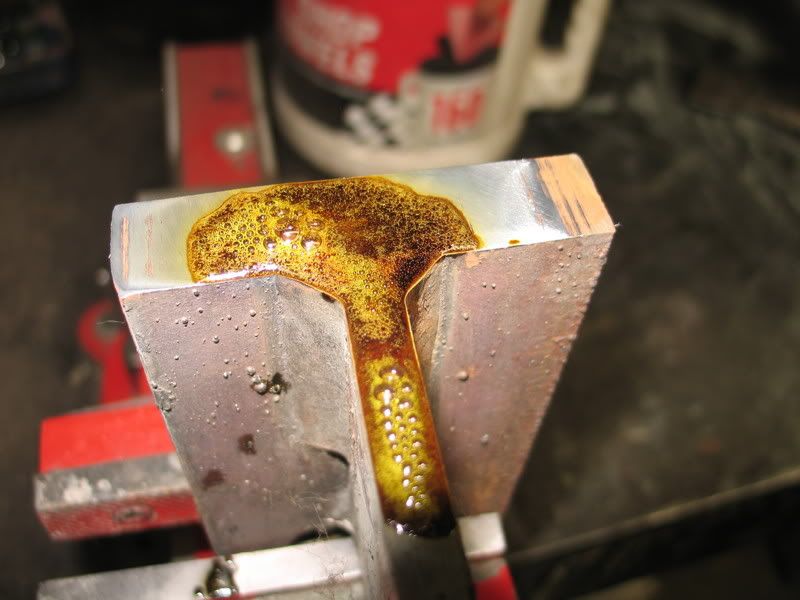
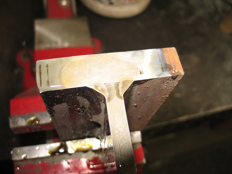
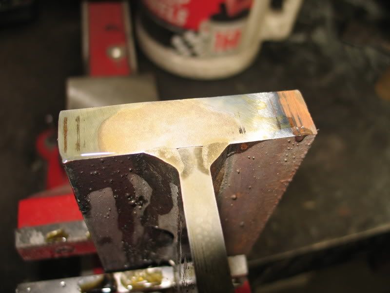
I'm guessing that you are talking about fillet welds on mild steel? If so, I would mock up a test plate with the 1/4" welded to the 1" and then section it(saw across the welded joint), take some fine grain emory cloth or a flap disc on a grinder and polish the cut to a nice shiny surface, put a few drops of battery acid (enough to cover the entire welded joint) wait a few minutes and when you see the acid quit working, take a spray bottle with clear water and rinse the part off(don't wipe it off with a rag or you will lose your etchings). This should show you exactly what penetration you are getting at the root and at the sides. This will also show you the HAZ as it will be a darker color than the rest of your etching.
Hope this helps,
Parent - - By 803056 (*****) Date 04-25-2007 12:39
JW, I like your macroetch solution, but it may not even require a macroetch to make your point. Several welders doing a simple fillet break test should show that GMAW using the short circuiting mode of transfer is going to produce questionable results. Based on my experience, the fillet weld break test should have a failure rate of about 90%.

Have each welder produce a single pass fillet weld (on one side of the joint) to join the 1/4 inch plate to the 1 inch plate. Clamp the 1 inch plate to the work bench, swing the 12 pound sledge hammer like a golf club and hope the 1/4 inch plate doesn't ricochet off a wall and kill someone (unless it's the engineer that specified this). You want to strike the ΒΌ inch plate on the side opposite the fillet weld. Pieces measuring 6 X 6 should work nicely for this demo. The 6 inch length will provide plenty of leverage to break the weld. The chances are, there will be little fusion to the 1 inch plate, especially if the engineer hasn't specified the removal of all mill scale before welding.

It never ceases to amaze me how many engineers with little welding background refuse to even consider the advice an experienced welder has to offer.

Best regards - Al

P.S. The safest location is on the handle end of the sledge hammer. Everyone else, duck behind something solid.
Parent - - By LandM Rad (*) Date 04-25-2007 21:35
This is going to make you laugh, the engineer has a degree in Argiculture, Farming!!!!  How he is in charge of the welding dept. is beyond me.  What he does is he reads from a book on how to weld a joint, looks for a "recomended" voltage, and has us weld at that voltage. Any more or less, he will throw away the job and have us start over (we are talking thousands of dollars of material that he threw out). It should be up to the welders on what to set the machine at.  For all he knows, the place where the book was written could have been at 3000 feet above sea level and 100% humidity. For crying out loud, he has told certified metallurgists that they are wrong about the HAZ and what not.
Parent - - By 803056 (*****) Date 04-26-2007 02:30
Hello LandM;

I don't always agree that the welder should be the person that makes all the decisions. I do believe in discussing the problems and potential solutions with engineering, welding (production), and quality control. More heads are usually better than one.

Most engineers learn about welding the same way welders do. Its all about on-the -job-training. Many welders jump from job to job and learn a little with each new job. Some welders learn a lot from their experiences and take full advantage of learning from the more experienced welders around them. In some cases, the welder knows-it-all before he gets to the job and learns very little due to his/her personality. If you are more than 25 years old you know what I'm talking about.

Engineers are humans too. They suffer the same human frailties welder do. Some engineers are willing to listen and learn, while others feel they are revealing a weakness when they ask for advice and don't take advantage of the information that is available by asking questions and seeking the advice of more experienced people. Like welders with poor skills, engineers with poor skills don't usually last very long. Their weaknesses will come to light soon enough. 

JW, nice photos!

Best regards - Al
Parent - By LandM Rad (*) Date 04-27-2007 00:27
I know, but this guy won't listen to reason.  He takes things that are correct and twists them into what he thinks should be right.  He has, on numerous occasions, struck down the smartest and most educated of us welders in our techniques.  I can not begin to start on all the stuff he has backwards.  We have told him and shown him proof and logic, but his attitude is "my way or the highway".  What I do is I play his game my way.  Only short circuit the mounts? Fine. I heat up the mount to 250 degrees, run a little hotter, and since the joint is a j-groove weld, I make sure that the WHOLE joint is used up in filler.
Parent - - By jwright650 (*****) Date 04-25-2007 12:54 Edited 04-25-2007 13:13
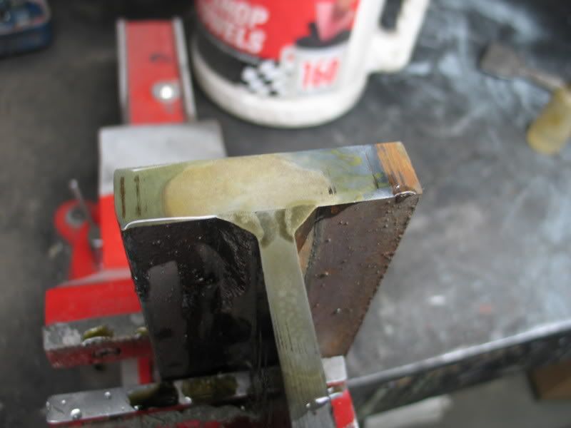
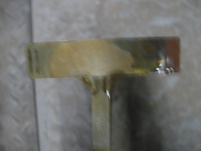
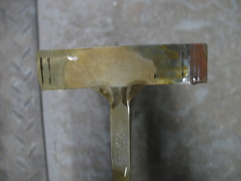
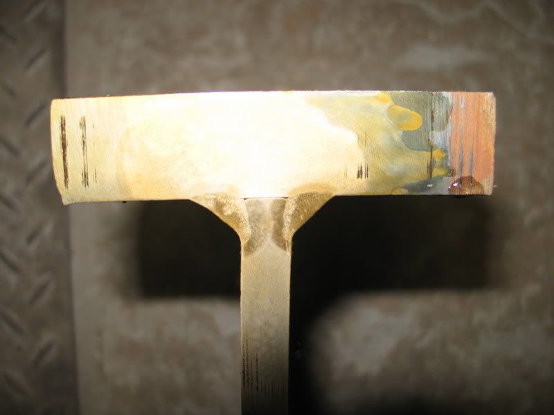
I just went out into the shop a few minutes ago and cut and etched a SMAW E7028 fillet weld so you could see the results of a macro etch. These pics were uploaded straight from the camera and from the thumbnails it was hard to see which were in focus and which weren't so I uploaded them all...so please excuse the repeats
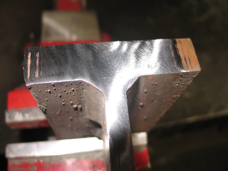
edit:added descriptions
Cut and polished:

Added the acid(I used nitric here in this pic, but battery acid will yield similar results and is easier to aquire):

After I rinsed the acid off with water(I took these pic right away, but it will rust so bad in a few minutes so that the etchings are no longer visible. To save these etchings, I quickly air dry and spray a clear coat of polyuethane over it to seal out the air. This will save your etching for several days before the rust takes over.


Parent - By js55 (*****) Date 04-25-2007 13:31
Another thing to keep in mind in addressing the crack concern issue is that there is nothing inherent to HAZ size that is crack inducive. If it were tons and tons of SAW welds (generally high energy and high heat input) would be cracking all over the place.
The exception would be certain higher alloys where thick liquid films are produced from high heat input that can generate the tendency to intergranular cracking. I am assuming you are not using a high alloy for lifting purposes.
Parent - - By LandM Rad (*) Date 04-25-2007 21:20 Edited 04-26-2007 00:18
nice pictures, I will give you a rough sketch of the mounts I am talking about, that will hopefully help you guys with my question.
Attachment: 22.bmp (784k)
Parent - - By jwright650 (*****) Date 04-26-2007 13:48
LandM,
Please forgive my ignorance, but I'm not sure what it is exactly that I am looking at in the sketch. Is this tank round? I assume this is a lifting lug that is being welded. Am I looking at the side, top or end of this tank in your sketch?

Sorry for being so thick skulled.....
Parent - - By LandM Rad (*) Date 04-26-2007 23:15 Edited 04-27-2007 00:28
You are looking at the front of a 14ft tall radiator that weighs 4 1/2 tons.  The tanks are square tubing shaped and the only the two mounts hold up the radiator in the mining truck. I know my sketch was "quick", but my graphic capabilities are limited. This is how the radiator sits in the truck.  Here is another drawing of the radiator.  I put on as much detail as I could.
Attachment: radiator.bmp (0B)
Parent - - By dasimonds (**) Date 04-30-2007 23:48
How about a pic of an actual radiator.
Dale Simonds
Parent - By LandM Rad (*) Date 05-04-2007 18:07 Edited 05-08-2007 23:29
The closest thing I can give you is our official website of our company.  I believe I can't just take a picture of the radiator due to the fact that our designs are kind of a secret, I think. Thats why I have no "measurements" in my sketches.  The site is www.mesabi.com.  Everything that you see on all the radiators are hand built by us.  Here is our product brochure.  On page 4 of the brochure, the 2 huge smokey black radiators are the Komatsu 830 and 930 models.  You can kind of see the two channel sections sticking out of the very bottom, thats where the mounts are located.  The channel is only for shipping purposes. And (pending on your screen quality) you can see on the bottom of the yellow radiator where the 2 mounts are.  They are at the very bottom, kind of located next to the employee's foot.  The mount location on that model is in the same location on the big Komatsus.  You can also refer to my sketches, they should kind of help explain what I am talking about.
Attachment: BROCHURE_FULL.pdf (546k)
Parent - By yorkiepap (***) Date 04-26-2007 00:26
Hey John,
Those are excellent photos and example of a proper fillet and your test to distinguish the area of penetration and HAZ. These kinds of photos are superb aids and teaching guides. I remember many years ago an 'ol timer(like I am now) showed me the same type of demonstration to provide the parameters to a former employer who was cheating on a couple of high load fabrications and wanted several of us to weld it without engineering approval. We managed to quell the issue without incident......Denny
Up Topic Welding Industry / Technical Discussions / Short circuiting thick steel

Powered by mwForum 2.29.2 © 1999-2013 Markus Wichitill