Not logged inAmerican Welding Society Forum
Forum AWS Website Help Search Login
Up Topic Welding Industry / Technical Discussions / Can we use all-around Symbol on Intermittent welds?
- - By playboy1898 (*) Date 10-25-2010 11:23 Edited 10-26-2010 00:35
Dear All:

Can we use all-around Symbol on Intermittent welds?
If we need this part weld all-arround Intermittent welds, how to make it clear?

Thank you very much!

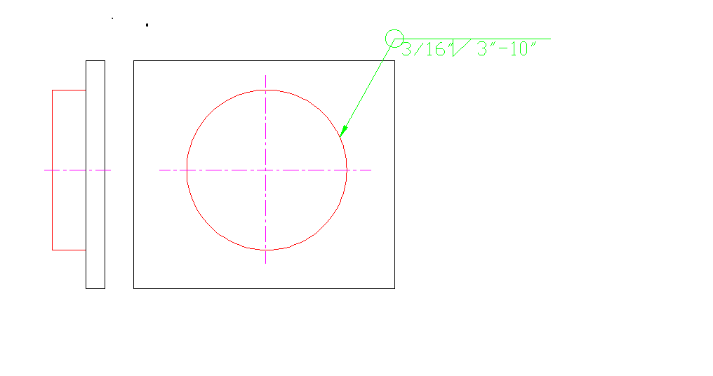
OK! I updated the drawing to make clear to discussing!

Thanks again!
Parent - - By 803056 (*****) Date 10-25-2010 11:57
The welding symbol looks fine. The intemittent fillet weld extends around the entire piece with no portions not welded. The note in the tail, "2 places", would indicate there are two identical joints that require the same extent, type, and size of intermittent weld.

Remember a couple of things about intermittent fillet weld symbols:

a) the weld size specified by the welding symbol is the minimum weld size. The limitation on undersized welds is dependent on the applicable welding standard.
b) the minimum length of each weld segment is the length specified by the welding symbol.
c) the maximum unwelded space between each weld is equal to the pitch dimension minus the weld length. The weld does not have to start or terminate at the ends of the joint. That requirement was dropped in 1976.

If a degree of precision with regards to weld placement is involved, the intermittent fillet weld symbol probably shouldn't be used.

Best regards - Al
Parent - - By playboy1898 (*) Date 10-25-2010 12:48 Edited 10-25-2010 12:56
Dear Al:

Thank you for your very good answer.

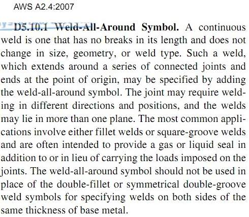
But AWS A2.4:2007 said: "A continuous weld is one that has No Breaks in it's length". No Breaks means the weld without any break. Intermittent welds has breaks. So we can not apply this All-around Symbol on the Intermittent welds.

Can you agree with me?

Thank you for your help!
Parent - - By jwright650 (*****) Date 10-25-2010 14:10
A dwg of the joint may be helpful, I read your question earlier, but refrained from answering because I thought a dwg may pop up later in the discussion, and then I could comment on it.

[quote]The weld does not have to start or terminate at the ends of the joint. That requirement was dropped in 1976.[end quote]

Al, I know many times intermittant fillets are called out and I'll have to re-read your comment to make sure that I didn't mis-understand,  but I like for our guys to tie the ends of the joint down with a fillet of the same length as called out in the symbol....just so the ends don't get ripped apart like a zipper.
Parent - - By eekpod (****) Date 10-25-2010 15:35
My first gut reaction is "no", because when I see the "weld all around" symbol I picture one long continous weld without any breaks or interuptions.
But I guess what you are trying to convey is that you need a continous stitch weld all the way around the part.  I think I get what you are trying to convey, but I'm not sure that;s the correct way to do it.
Just my thoughts
Parent - - By 803056 (*****) Date 10-25-2010 17:04 Edited 10-25-2010 17:07
Hello John;

I agreed with your position regarding starting the intermittent weld at the end of the weld joint at one time, but in 1976 the note that required all intermittent fillet welds to begin and end at the ends of the joint was dropped from the A2.4 standard.

I wrote a letter to the committee pointing out the omission of the note. The response from Dr. Green, the chairman of the subcommittee at the time, was that the requirement to begin and terminate the weld at the ends of the joint was a workmanship issue, not a function of the welding symbol. If the designer wants the weld to initiate at the end of the joint, then he must use something other than the intermittent welding symbol.

In a similar manner, there are no tolerances associated with the intermittent welding symbol. As long as the fillet weld size meets the size requirement, as long as each weld increment is at least as long as that specified, and as long as the unwelded spaces between the weld increments does not exceed pitch minus the increment length, the weld meets the welding symbol and all is good. Anything more stringent than that falls under workmanship, which would have to be addressed by the applicable welding standard or in-house quality control requirements. The bottom line is that a weld that is continuous without any breaks meets the requirements of the welding symbol, but perhaps not the workmanship requirements.

Meeting the requirements of the welding symbols is not the same as meeting the workmanship requirements of the welding standard or company's standards. Never the twain shall be confused.

Regarding the post about the weld being continuous; that was taken from the commentary, which is not a requirement, but intended to help understand the intent of the standard. So, in essence, the intermittent welding symbol implies the weld is continuous, the size does not vary (i.e., the leg dimension from one segment to the next is the same) and each weld increment is the same length as the next, around all the nooks and crannies of the joint without interruption. Thus the requirement of the "weld all around" symbol is met, i.e., the intermittent weld is continuous all around the entire joint.

By the way eekpod, what the hell is a stitch weld? Is that in A3.0?

Best regards - Al
Parent - - By Shane Feder (****) Date 10-25-2010 23:38
Good morning Al,
"Stitch" weld is commonly used in the Southern Hemisphere as another meaning for intermittent fillet weld.
Not sure of the origin of the term.

If the item to be welded is a square or rectangle and you require intermittent fillet welding on all four sides would it not just be easier to put the symbol by one of the corners with two arrows going to the nearest two sides. Have all the relevant information above and below the reference line and you will have intermittent fillet welds on arrow side of part (x 2) and intermittent fillet welds on other side of part (x 2).
Seems as if it would be a lot less confusing,
Regards,
Shane
Parent - - By 803056 (*****) Date 10-26-2010 03:40 Edited 10-26-2010 03:50
Hello Shane;

You missed my point. I was hoping to raise the bar of technical literacy here in the Forum. Stitch weld is a "nonstandard" term according to AWS A3.0. It's kinda like shielded metal arc welding versus "stick welding." Which is the "common" term and which term is correct term? Most of us that work with AWS terminology will agree that "stick welding" is what someone does when they try to weld with SMAW for the first time. Some people think those fused electrodes attached to the practice plate are "studs", but most of us know better.;)

When it comes to welding symbols, there are usually several ways to specify the same welds. Each is correct, but usually one welding symbol is easier to interpret or takes less time to draw or fits the limited real estate of the drawing better.

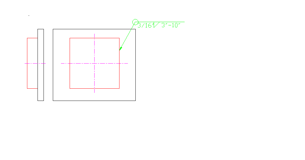
Consider how many ways you could specify the welds in the following sketch. I can think of at least four and each is correct.

Best regards -Al
Parent - - By DaveBoyer (*****) Date 10-26-2010 03:49
Perhaps it is nonstandard by A3.0, but there have been a lot of smaller [150-250 amp] MIG welders sold that have a "spot/stitch" function to deliver this type of weld semiautomaticly.
Parent - - By 803056 (*****) Date 10-26-2010 04:14 Edited 10-26-2010 04:19
That's akin to saying the welder that rapidly depresses the trigger of the GMAW gun is pulse welding. Just because the marketeers employed by Miller, Lincoln, ESAB or any other marketing concern (OK, let's add welders, inspectors, and engineers to the list) think up another spiffy term doesn't make that term technically correct.

There is literature available that still refers to the person that welds as the weldor and the root face as the land. While American industry says they have adopted AWS terminology in accordance with A3.0, there are still welding standards that include nonstandard AWS terminology. I'm not saying it is wrong, but I am saying that the use of standard terminology minimizes the chance of miscommunicating our thoughts and ideas. Example of nonstandard terminology can be found in a number of AWS' welding standards. It pretty sad when the AWS committees can't take the time and effort to check their standards for proper terminology. We also see plenty of examples of miscommunication here in the Forum when nonstandard terminology is used.

Does it make me a technical snob to point out the use of nonstandard terminology? I hope not. I thought the functions of the Forum were to educate and enlighten. Were that not the case, I don't think we would expend the time and effort to explain our positions when we disagree. The discussions would quickly reduce to "Hey, dummy, that's not right!” let's move on to the next opinion. Wait a minute; I think I remember a few of those threads. ;)

Best regards -Al

P.S. I see the sketch that started this thread has changed. When the member is a round, the "All Around" symbol is not necessary and considered redundant.
Parent - - By playboy1898 (*) Date 10-26-2010 05:02
Dear Al:
Thank you for your comments.
I agree with you. Standard terminology make less miscommunication and misunderstanding.

Yes! I add the parts on the sketch.
As you comment, If the part is not the round, the "All Around" symbol is necessary?

I think the member is a round or not is not the Key reason of apply the "All Around" symbol.
Parent - - By 803056 (*****) Date 10-26-2010 10:43 Edited 10-26-2010 10:47
A continuous weld, that is a weld specified by the welding symbol without the length indicated, extends along a joint to the point where there is a change in direction. If the welding symbol does not indicate the length of the weld, it would only go from one corner to the next. The weld would stop where the welder has to change the direction of travel. The exception to the rule is when the member is round or nearly so, in which case the weld would be continuous around the part. Therefore, if the weld is indeed continuous around four, five, six... or ten sides, the weld all-around symbol is appropriate if the weld is the same throughout. The weld all-around symbol is not needed when the part is round or nearly round.

My interpretation was based on the intermittent fillet weld being continuous around the joint, i.e., the size of the weld does not vary, the length of the weld increments do not vary, and the length of the unwelded spaces between weld increments do not change (based on the welding symbol). However, if the intermittent fillet is not continuous around all the sides of the part, the all-around symbol is not applicable, nor does the welding symbol depicted by my sketch actually indicate the weld is "almost all-around."

The sketch in my previous post is just one of many I have collected over the years where designers have come up with their own welding symbols. That is bad practice for any designer, just as it is bad practice when a welder or inspector uses a nonstandard welding term. It only confuses other people.

The comments I made regarding the weld all-around symbol and the intermittent fillet weld is only my opinion on the subject. Other members of the Forum are free to offer their opinions as well. Their interpretation may very well be more in line with the intent of A2.4 than mine.

The only opinion that holds water is one obtained from the AWS Committee on Welding Symbols. My advice would be to ask the AWS committee for an official interpretation.

Best regards - Al

P.S. One addition point of information, the units of measure, i.e., inches, feet, mm, etc., are not normally shown on the welding symbol.
Parent - - By playboy1898 (*) Date 10-26-2010 11:18
OK!
This forum is very good.
Especially there have a group of very nice welding people to discuss any welding problems.

But I still not understand the "all-around Symbol on Intermittent welds".
Intermittent welds is breaking welds.
So I still think "all-around Symbol on Intermittent welds" is not permited by AWS A2.4:2007.
Parent - By jwright650 (*****) Date 10-26-2010 12:04
Now that I've seen the dwg, I don't have a problem understanding that the intended weld is to be intermittant (3" of 3/16"fillet weld in every 10" of circumference) for the entire perimeter of the round pipe or square tubing. I think it would be clear if my shop guys saw that on a dwg.

I think the key here is good communication between the designer and the welder...which is perfectly communicated through welding symbols.
Parent - By jwright650 (*****) Date 10-26-2010 12:16
OK since we are talking about whether the message is clear or not....I printed the dwg and showed it to several of my welders on the shop floor. I asked them,  "if you saw this on a dwg how would you weld it?"

Every person that I asked said they would place a 3/16" fillet weld, 3" long, spaced @ 10" center to center around the perimeter of the pipe, or tubing.

One thing is being assumed here though, and certainly the bill of material would clarify any doubts...but is the pipe or tubing large enough to get 3" of weld for every 10" of circumference?
Parent - - By fschweighardt (***) Date 10-26-2010 11:22
In every job we send out for bid, one of the first things we specify is: "all communication between the Owner and the Contractor will use welding terminology and symbols per the most current commercially available edition of AWS A3.0 and AWS A2.4"
Parent - By ssbn727 (*****) Date 10-26-2010 19:35
I think that is the main point which Al is trying to convey, and it isn't limited to just AWS because as one knows, API, EN & other welding codes do indeed use some different terminology as well. Excellent observation btw! ;)

Respectfully,
Henry
Parent - - By 803056 (*****) Date 10-26-2010 19:51 Edited 10-26-2010 19:59
It the designer has any doubt that a welding symbol will be interpreted correctly, a different welding symbol should be used. If there is no welding symbol that clearly delinates the welding requirements, a sketch of the weld is perfectly acceptable.

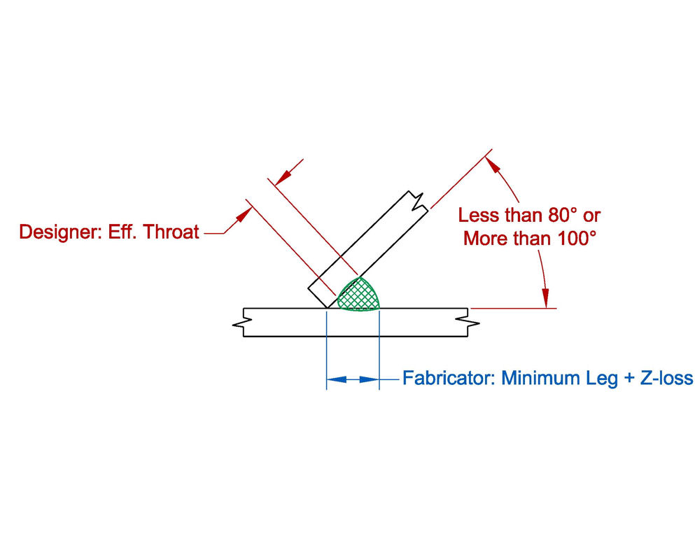
A good example of a situation where a standard welding symbol is not appropriate would be the welded skewed joint. When the dihedral angle between the two memebers is less than 60 degrees the designer must consider the Z-loss factor. The drawing requirements for such welded joints have evolved over the years in AWS D1.1. The weld between the skewed members is no longer referred to as a fillet weld. It is my opinion that the weld is neither a fillet weld nor a groove weld. One of the basic premises of a fillet weld is that there is fusion to the root, but in the case of skews between 60 degrees and 30 degrees the presumption of fusion to the root is not the case, i.e., the requirements to consider the Z-loss must be factored into how the weld is sized. 

Clearly, the weld between the two members is not a fillet weld, so the fillet weld symbol is not appropriate when specifying the weld. Likewise the weld between the skewed members does not meet the requrements of a complete or partial joint penetration groove weld. The weld is on the joint rather than in the joint. therefore a welding symbol describing a PJP or CJP groove weld is not appropriate. As a matter of fact, when sizing the weld, the minimum weld size required is based on the thickness of the base metals as if it were a fillet weld. However, the designer has to define the weld based on the throat requirements and the fabricator has to specify the weld based on the leg requirement with due consideration for the Z-loss and possibly the back-up weld in the case of a T, Y, or K connection.

When neither a standard fillet weld or groove weld is required, perhaps the easiest means of conveying the information required by the fabricator and the welder is for each entity, i.e., the designer and fabricator, to simply show a cross section through the joint with the appropriate dimensions as required by D1.1 and as depicted below.

It is logical for the fabricator to be given the responsibility to detail the sketch of the weld on the shop drawing with the required leg dimensions because it is the fabricator that determines what welding process is to be used and the position in which the weld will be deposited. The Z-loss is a function of the dihedral angle, welding process, and position in which the weld is made. The designer more than like will not know who the fabricator will be, what welding process will be selected, or the position in which the welding will be performed. The designer's task is to provide the fabricator with the required effective throat that is sufficient to transmit the design loads.

References: AWS D1.1-2008 Clause 2.2.4 (1) and (2), Clause 2.2.5, and 2.2.5.2 (1) and (2), Clause 2.3.3.2, Clause 2.3.3.3, Clause 2.3.3.4, Table 2.2 (Z-loss), Clause 4.12.4.2 (modifications for tubular structures with a back-up weld), and Table 5.8 (minimum fillet weld size).

Best regards - Al

P.S. my attempts to resize the sketch clearly failed.
Parent - - By Bob Garner (***) Date 10-27-2010 17:09
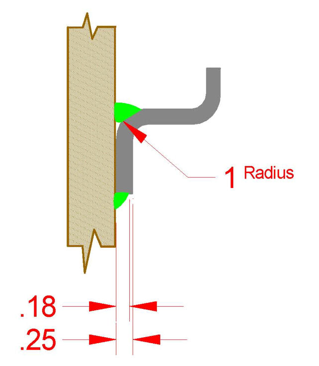
As a structural engineer, I am finding it more and more important to detail some welds more fully than we were taught.  Right now I'm designing some floor plates that will have angle stiffeners.  The stiffeners must be spaced 3/16" away from the plate to enable galvanizing to enter the joint (I wouldn't have recommended this detail but that wasn't my choice.)  So how do I draw a weld symbol for the "fillet/groove" weld between the angle leg and the plate?  I'm just going to have to draw a cross section of the weld showing the minimum throat and where this occurs.

The intermittent welds not starting and terminating at the ends of the welded part concerns me, and I will cover that in the future by notes in the tail or a more better drawing of the actual weld.

Communication is Everything!

Bob G.
Parent - By 803056 (*****) Date 10-27-2010 17:42 Edited 10-27-2010 17:46
None tells the fabricator more than a cross section depicting the weld you require.

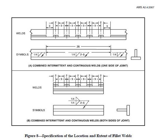
As for the welds at the ends of the joints when intermittent fillets are required, here is a cut from A2.4-2007 that shows just about what you are describing. The only information not shown in sketch at the top of the page is the length of the welds at the ends of the joint.

The lower sketch is misleading if it implies the intermittent welds start and stop at the ends of the joint.

Best regards - Al
- - By eekpod (****) Date 10-27-2010 10:31
Playboy 1898
Don't forget, they can always put notes in the tail to clarify.
Parent - - By strat (**) Date 10-28-2010 12:45
Playboy1898, I just received a drawing, 8" pipe with 1" plate both ends with a welding symbol with a intermittent weld symbol with a weld-all-around symbol
If someone could tell me how to paste it on here I will, cant figure it out, ive got it scanned
Strat
Attachment: E691.pdf (206k)
Parent - - By jwright650 (*****) Date 10-28-2010 12:52
Use the attach button, and then use the browse button find the file on your computer to upload it into your post(click embed).
Parent - - By strat (**) Date 10-28-2010 13:27 Edited 10-28-2010 13:31
Thanks John, I have it attached to my last reply
Strat
Parent - - By 803056 (*****) Date 10-28-2010 17:24
From the sketch/drawing, it appears to be a case where the designer either doesn't know the requirements of D1.1, doesn't know the difference between E70XX and low hydrogen electrodes, or the designer is giving the fabricator the opportunity to qualify the WPS by testing.

It is simply amazing how many designers assume all E70XX electrodes are low hydrogen.

It is scary how many designers (including engineers) have no clue about the influence of diffusible hydrogen on the integrity of a weld.

One must not forget that their ignorance is the basis our continued employment and prosperity.

Long live ignorance.

Best regards - Al
Parent - - By jwright650 (*****) Date 10-28-2010 18:22
Al,
re: E70XX
We have mentioned that very thing in our detailing SOP manual so that our detailers will know that when they work for us they must use this designation "E70XX-LH" on our shop drawings. It came up in one of our AISC audits many years ago, so we took care of it then and spelled it out in our detailing SOP.
Parent - - By 803056 (*****) Date 10-28-2010 19:09
It is amazing what problems can be avoided with a little forethought.

However, is it the intent to limit the welder to using shielded metal arc welding with the note you mentioned?

Would a note such as: "The filler metal/process combination shall produce a weld with a minimum UTS of ___________ ksi and shall be capable of meeting the low hydrogen requirement of no more than ____ ml of diffusible hydrogen per 100 grams of deposited weld metal." be more generic and applicable to any welding process selected by the fabricator? The blanks could be filled in with the appropriate UTS and the values of "16", "8", or "4" to indicate the maximum amount of diffusible hydrogen permitted.

16ml [H]/100 g would meet the requirements of a standard generic E7018 that has been properly stored in accordance with D1.1. The notation would permit the fabricator to select any FCAW, GMAW, GTAW, or SAW filler metal/electrode as as long as the electrode (and flux) is capable of meeting the minimum UTS and maximum hydrogen limitations.

Best regards - Al
Parent - - By jwright650 (*****) Date 10-28-2010 20:28
Al,
I like your note, but we are talking to detailers here...LOL, less is more with them. If I get too wordy they want to charge me more money to add it to the dwg...., like they have to hand print it on every sheet or something like I used to do when working off a manual board with real graphite in my pencil...LOL

No the intent was to use 70ksi-LH electrodes UNO, contract docs would specify if something less than a H16 was required

We need to relook at that because at that point in time we had E7018, E7028, and E70T-1 exclusively and fit the E70XX-LH nicely....since then we have added an E71T-1 to our arsenal.
Parent - - By 803056 (*****) Date 10-29-2010 04:25
But how does the requirement get passed on to the welder if not through the shop drawing notes?

Hark, did someone mention "WPS?"

Curses! The WPS is written by an old ASME hand who learned the minimalist ways, "Weld here as required. Use E7XXX! All grooves, all fillet."

"What the Fxxx!" crys young Arcstriker.

"Arcstriker, how stupid can you be. Any welder knows you can't use E7010 on A992!" says the ASME Minimalist.

"Cause your stupid WPS says I can use any 70 ksi rod!", whines young Arcstriker.

"But your a welder, you're suppose to know better!" responds the ASME Minimalist.

Let's end the story here before the coming of the blows that follow, the recriminations, bloody noses, clumps of hair, fingers clasped tightly around throats, and chewing tobacco stains on the ASME Minimalist's shirt.

The horror, the horror of it all, I can't recount the aftermath any further!

It could have ended so differently, if just .........

Best regards - Al
Parent - By jwright650 (*****) Date 10-29-2010 10:23
If I don't don't provide anything other than LH processes and electrodes then there is no problem mistakenly using something else. Kind of hard to go to the rod oven and grab a a 6010 or a 7010 when there are none in the oven...LOL

BTW, our WPSs already have the correct electrodes spelled out for the welder to use....so there goes his excuse and he's busted for bringing in his own rods from home and using them on A992...LOL.

Our FCAW electrodes already have the correct LH designations for any seismic work, we just have to invoke the exposure limits on the rolls of wire once the project starts which is tracked by QC and logs are kept and monitored to prevent an over accumulated exposure time.

Any special requirements are spelled out on the drawings and or memos to the shop for any projects that get something other than the norm.
Parent - - By strat (**) Date 10-28-2010 19:16
Not sure if the engineer drew this sketch or had it drawn but just off this sketch look at the rfi's. 1-E70XX ?  2.is the plate round or square, just states 1"x1'
3. is it for sure an intermittent weld or full lenght, 4. 8" XS pipe, that doesnt tell me a lot
Strat
Parent - - By 803056 (*****) Date 10-29-2010 04:04
Let's not overlook the violation of D1.1's minimum length requirement for intemittent fillet welds. Clause 2.3.2.5 requires each segment to be at least 1 1/2 inches in length.

"Look Jane, Look!"

"See Jerry draw."

"Jerry can't read."

"Jerry does not own a copy of D1.1."

Best regards - Al
Parent - - By jwright650 (*****) Date 10-29-2010 10:24
Who is Jane and Jerry?...LOL :-)
Parent - By 803056 (*****) Date 10-29-2010 18:33
What's D1.1?

One of the first questions I ask the fabricator during an audit is, "What color is the cover of AWS D1.1?"

You would be amazed at how many times the response is "Blue?"

Best regards - Al
Up Topic Welding Industry / Technical Discussions / Can we use all-around Symbol on Intermittent welds?

Powered by mwForum 2.29.2 © 1999-2013 Markus Wichitill