Not logged inAmerican Welding Society Forum
Forum AWS Website Help Search Login
Up Topic Welding Industry / Technical Discussions / Tolerances in T-joints
- - By ustundag Date 07-15-2014 08:22
Dear All,
In an ongoing cable-stayed bridge construction, we have a case where 2.5 m (8') diameter, 40 mm thick steel piles are CJP welded to bottom flange of a pile cap (bottom flange thickness 60 mm). The pile cap rests on nine vertical piles of same size. As a result of the final installed positions of some of the piles and the pile cap in the field, root opening and tolerances at a number of weld joints cannot be satisfied as required in AWS D1.1 Figure 3.4, 5.22.4 or AWS D1.5 Figure 2.4. In other words, the root gap is larger than that of allowed. Gap is in the range of 20-25 mm. How can we improve this situation? I am not sure if building up the pile section with welding is reasonable. Thank you so much for your input.
Attachment: SketchT-joint.PDF (105k)
Parent - - By welderbrent (*****) Date 07-15-2014 08:52
It may not seem reasonable, but if I am understanding your situation correctly it is the code acceptable method for taking care of your situation.  You must weld in order to build up the edge to bring it within the root opening tolerance without bonding the two sides of the joint until after the acceptable opening has been achieved and it is prepared for welding.  Then you weld as normal. 

He Is In Control, Have a Great Day,  Brent
Parent - - By ustundag Date 07-15-2014 11:04
Brent, the root opening we have at hand is larger than the required 1/8" (3 mm). What can be done to improve this situation? Do you know any code requirements for a situation like this? Thanks!
Parent - By jwright650 (*****) Date 07-15-2014 11:16 Edited 07-15-2014 11:19
If the root is larger than 3/4" as noted in Clause 5.22.4.3, then you default to Clause 5.22.4.4 and ask the engineer of record for permission to build it up with weld before welding the joint.

EDIT*
Whoops! I replied using AWS D1.1, I don't have my copy of AWS D1.5 with me right now to reference...but I'm going to assume that it has similar language for joint tolerances.
Parent - - By welderbrent (*****) Date 07-15-2014 17:29
Ozan,

First, this is why we usually ask people for more information, things start coming out after the OP that change things.
Second, John hit the main part, ask the engineer.
Third, Figure 3.4 covers many Joint Designations.  We really need to know which joint.
Fourth, We also need to know which process.  That effects how things can be handled and what the actual opening and the permissible tolerances are. 
Fifth,  As I stated, you close the root opening by welding the edge and then preparing the profile (groove angle, bevel angle, etc) so that it is ready for the correct root opening weld procedure with the engineers okay.

He Is In Control, Have a Great Day,  Brent
Parent - By ustundag Date 07-16-2014 14:27
Brent,

I'm attaching a sketch below showing the joint designation and the welding process chosen. If you have AWS D1.1 2008 handy, it is the top figure on Page 98, only to be rotated 90 degrees clockwise. Welding process chosen by the shop is SMAW + FCAW, with 45 deg. groove angle.
Position of welding is overhead (4G) since piles are located underneath the pile cap, where each pile is accessible with a manhole. Welder will mostly have to work from the inside of the pile up towards the bottom flange of the pile cap; and the cap will provide some restriction (please see the sketch).
Thanks to Al for his excellent sketch and photo!
Since welding position in our case is OH, do you think the qualified welder would be able to deposit weld vertically to bring the root opening to acceptable level?
Attachment: SketchT-joint.PDF - Joint designation and welding process chosen (p. 98 of AWS D1.1 2008) (115k)
- - By 803056 (*****) Date 07-15-2014 18:51 Edited 07-15-2014 18:56
Brent is steering you in the right direction.

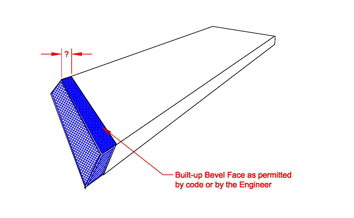
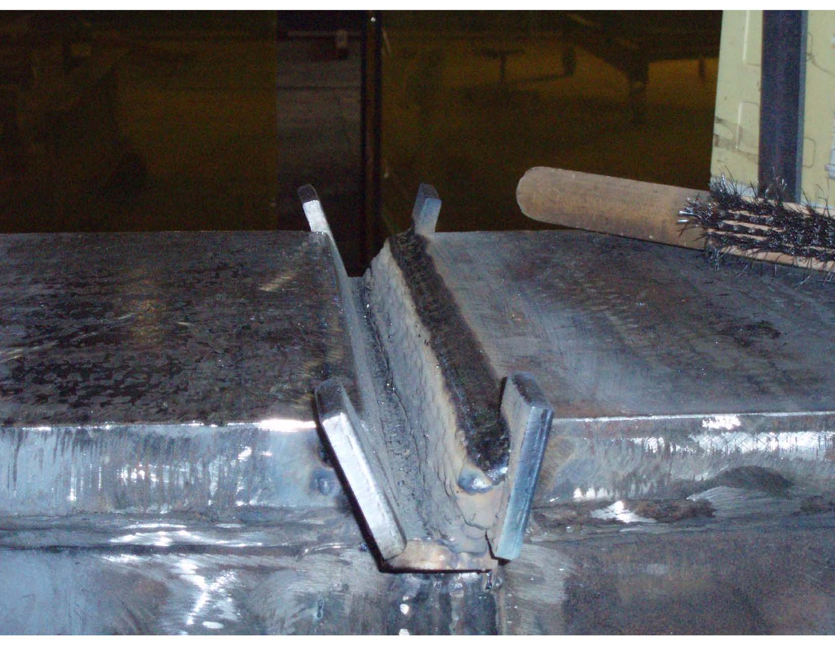
The sketch shows the repair and the photograph shows an actual repair of an excessive root opening in a butt joint. The build-up (surfacing weld) has been deposited to close the root opening. Now the welder has to clean up the weld beads to ensure the deposit is sound and the production weld has a fighting chance of being sound. If the surfacing weld has a poor profile, it will be a problem for the welder to deposit sound weld in the groove.

Al
Parent - - By welderbrent (*****) Date 07-15-2014 23:30
Boy Al,

You're getting pretty good with those sketches and that photo is a great example of exactly what is referenced for the OP.

(Stealing some more instruction aides donated by the notorious 'Al'-  :lol: )

He Is In Control, Have a Great Day,  Brent
Parent - - By Lawrence (*****) Date 07-16-2014 14:47
I have NOTHING to add to this conversation.... Except.

Run-off tabs !

Boys and girls... They are worth the time and effort...

Great Pic  Al :)
Parent - By jwright650 (*****) Date 07-16-2014 16:42 Edited 07-16-2014 16:46

>Run-off tabs !


Amen to that!

another example
Parent - - By ustundag Date 07-16-2014 14:43
Al,

Thank you so much for your excellent sketch and the photograph, showing exactly what I was looking for! The only difference is the position, where in our case the welding position is OH. I have attached a sketch up in the thread (with a file name "Sketch T-joint.pdf"). Hopefully, you will be able to view it.
It is great that section can be built up to bring the excessive root opening to acceptable level. Now I began to wonder if this repair can be done on a vertical face of the pile wall; please keep in mind that we have the steel pile cap up above which is causing restriction to the whole process. All pile to pile cap welding will be done in the field.
One more question regarding your photo, how did the Engineer respond to the excessive root opening and how was the approval process?

Kindest regards,
Ozan
Parent - - By 803056 (*****) Date 07-16-2014 19:50 Edited 07-16-2014 20:29
Let me make sure I have the right picture of what is going on. The piling is pipe with a piling cap spanning the top of several (more than one) pile. As a result of the piles being cut to different lengths, the root open can be as much as 1 inch (25 mm).  There is no access to the ID of the piling, so all the welding must be from the outside.

The first thing I would do is verify (from the Engineer) the pilings are considered to be statically loaded connections. Assuming they are, you can use a backing bar on the inside circumference of the piling. The welders can start the weld on the underside of the piling cap as a fillet weld, leaving the connection to the piling free to expand and contract. It is important that the backing bar not be welded to the piling until the root opening is reduced to an acceptable width. Once the root is built up, the remaining weld can be completed to tie the cap to the pile.

The weld should be deposited using low hydrogen electrode. Take pains to ensure the electrodes are properly stored and the exposure time for the covered electrodes are complied with.

Weld Tabs per Annex K (D1.1-2006 ). They are the first thing I look for when inspecting groove welds at splices, moment connections, etc. If there are no tabs, I grind the ends of the groove to reveal the incomplete fusion and then the fun begins.

Best regards - Al
Parent - - By ustundag Date 07-17-2014 15:06
Please let me make some clarifications and provide additional details about the joint(s) in concern...
The pile cap is 50' by 50' steel box that is 8' deep. It spans over 9 piles, that are configured as 3x3 grid, with 21' c. to c. spacing.
Each pile is 8' in diameter with a wall thickness of 1 9/16 inches (40 mm).
Piles are accessible from the inside with manholes provided thru the pile cap.
As a result of the piles being cut to different lengths and due to the final installed positions of the piles & the cap in the field, the root opening can be as much as 1 inch (25 mm).
The welding can be done from the inside of the piles while allowing for backgouging from the outside. Clear distance from pile to pile is 13' horizontally.
Contract plans call for one-sided CJP weld from the inside of piles.
Pile cap supports one of the pylons of a cable-stayed bridge.
The bridge is located in a high seismic zone.
Hope this helps...
Parent - By 803056 (*****) Date 07-18-2014 03:04 Edited 07-18-2014 03:35
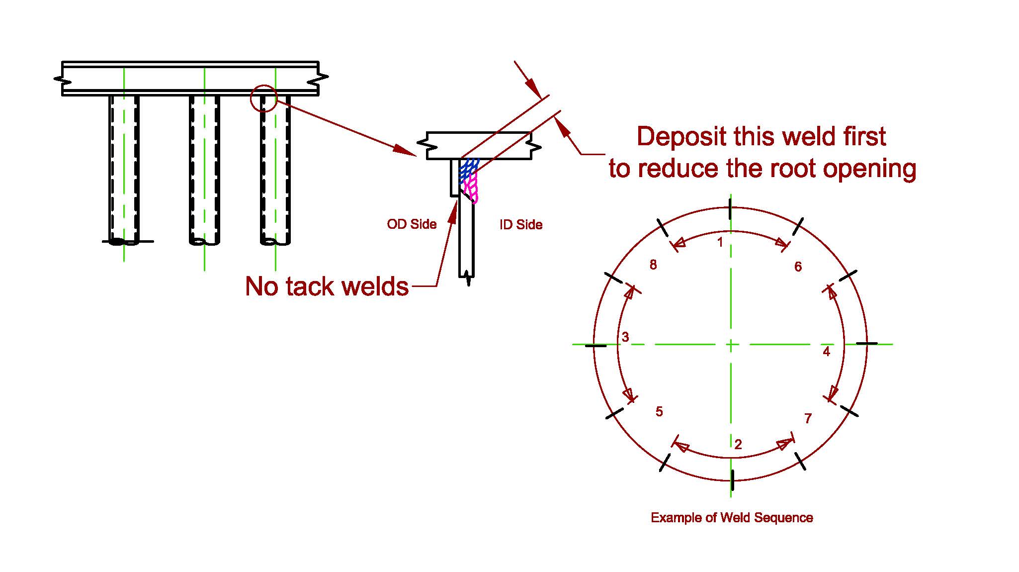
I would still opt for the backing ring. Place the backing ring on the outside of the pile, weld from the inside as shown on the sketch I attached yesterday. The difference is you are welding from the inside instead of the outside. Once the piling is welded, back gouge the backing ring from the outside. I'm sure the welder will gouge into the weld somewhat, but welding from the outside should be easy.

The backing should be tack welded to the pile cap, not the piling. As you weld the large fillet required to close the root opening, the backing will be drawn tight against the outside of the piling. As you fit the backing around the piling, you can weld lugs on to the backing so it can be clamped tight to the piling, but it has to be free to float until the root is closed sufficiently to deposit the root bead as a single pass. The welders should balance the residual forces by welding sections on opposite sides. Divide the ID circumference into 12 equal lengths. Weld from 11:30 to 12:30, then 5:30 to 6:30, then 8:30 to 9:30, then 3:30 to 4:30, and so on until the entire ID is welded. You can use a block technique with cascaded ends to minimize the need to grind every start and stop.

What welding process are you planning on using?

Best regards - Al
Parent - - By kcd616 (***) Date 07-16-2014 21:16
Al,
what software program for the drawings?
thanks,
Kent
Parent - - By 803056 (*****) Date 07-16-2014 22:38
An old version of AutoCAD.

Al
Parent - - By ssbn727 (*****) Date 07-18-2014 08:35
The piles remind me of the missile tubes we welded up in "Rotten" Groton, Ct when we were building the first 3 Ohio class Trident "Super Boomers" back in the late 70's...

A point of caution... The staging you're going to have inside these pilings must be checked to be sure they're erected properly... What I mean by that is to make sure if you're going to temporarily weld any angle iron or tubing to the I.D. of the pile - to make darn sure to preheat the inside of the pile first before welding anything on to the pile wall!!!

I personally had a "Bad Day" back then because of some jerk who didn't check to see if the missile tube I.D. wall needed to be preheated first before welding onto the tube wall...
Well, they didn't even though the safety inspector tagged it to be safe to work on... What was the result of this oversight?

While I was welding on to an over machined area which was inside the tube made out of HY-100 steel, all of a sudden I felt as if I was falling and then THUD!!!! When I came to
I was at the bottom of the missile tube with both Humerous (It's NOT FUNNY AT ALL!!!) bones broken in my arms, a busted clavicle, and the bottom bone of my spinal cord fractured...
It could have been much worse!!!:surprised::roll::twisted::cool:

The timing of the incident couldn't have been worse also because it happened just before lunch break as everybody inside were massing by the second deck opening to climb down the stairs and head out of the yard for lunch so nobody was inside the boat to hear me yell until the first few got back in from lunch and when they found out what happened and figured out what happened I was already down at the bottom of the tube being lifted out with a crane and onto a boat to get me across the Thames river to the hospital in New London, CT... It took me around six months to recover and return to work...

So please make darn sure if you're going to weld something temporarily on to the wall of the pile and if the material & thickness calls for it, preheat it first!

Respectfully,
Henry
Parent - By 803056 (*****) Date 07-18-2014 21:27
Excellent advice. It is amazing how people will take short cuts when it is someone else that will be using the apparatus.

Al
Up Topic Welding Industry / Technical Discussions / Tolerances in T-joints

Powered by mwForum 2.29.2 © 1999-2013 Markus Wichitill