Not logged inAmerican Welding Society Forum
Forum AWS Website Help Search Login
Up Topic Welding Industry / Inspection & Qualification / How To Measure Plate-To-Pipe Fillet Weld?
- - By thirdeye (***) Date 12-04-2014 19:24
The subject says it all... I guess I need guidance or clarification since the members are not only NOT at 90°, but curving away. Is this configuration shown (with the yellow arrow) treated as a skewed fillet, or is there another option?  Drawing simply calls out a 1/4" fillet all-the-way-around.  All input appreciated.

Parent - - By onoberhie Date 12-04-2014 20:17
I think the best way to measure the fillet size of the plate to pipe fillet as shown on your question is to place your measurement fillet guage with its longest side parallel to the plate surface pointing towards the pipe circumference .
Parent - By welderbrent (*****) Date 12-05-2014 16:46
BTW, Henry (newbie Henry that is, not our normal contributor),

WELCOME TO THE AWS WELDING FORUM!!

I did not miss the contribution of a new member here.  Thanks for your contribution. 

He Is In Control, Have a Great Day,  Brent
Parent - By SCOTTN (***) Date 12-04-2014 20:23
I don't take it as a skewed fillet.  I've always just put the end of my fillet gage against the face of the plate to verify the vertical 1/4" leg, and the bottom of my fillet gage to the face of the pipe to verify the horizontal 1/4" leg, and then verify the fillet throat.
Parent - - By welderbrent (*****) Date 12-04-2014 22:10
Question #1 is always going to be, is there a code involved and if so, which one?

Having accomplished that, for most applications that is 'technically' going to be one of those special cases that should have the welding reference line with a note to see the detail and have the engineer clarify all questions with a detailed sketch of what he wants.  More than likely, the throat will be the most critical and it may need to be proven that the welder can accomplish the weld strength criteria with the size "fillet" weld being completed.  To do this will require a PQR.  Because of the angle, it is more properly a skewed joint and as such will require longer legs than normal to get the throat with the strength sought for the application. 

He Is In Control, Have a Great Day,  Brent
Parent - - By thirdeye (***) Date 12-04-2014 22:48
Yes, you are correct Brent. 

The code is AWS D1.1-2010.  The welding symbol displays the basic "both sides" fillet symbol and size indicated is .25, within the tail is the abbreviation for typical "Typ".  There are no special notes associated with the detail itself.
Parent - - By 803056 (*****) Date 12-05-2014 03:06
I go along with Brent's position that it isn't a fillet weld since the angle between the two members is greater than 100 degrees. A welding symbol specifying a fillet weld isn't appropriate if AWS D1.1 is applicable.

The Engineer's design drawing would have to specify the Effective Throat. The fabricator would be responsible to specify the required Leg dimensions needed to provide the required Effective Throat.

It would be best to ask the Engineer for clarification. The chances are that the Engineer is basing the size on the assumption the weld is made using a 70 ksi filler metal and the allowable stress is 0.9 kip per 1/16 inch leg per inch of weld length which would be the case if it was an actual fillet weld as defined by AWS D1.1.

Best regards - Al
Parent - - By thirdeye (***) Date 12-05-2014 12:19 Edited 12-05-2014 12:31
Al, I appreciate your views and the fact that both you and Brent approached this question from a design and engineering perspective.

In some research last evening  I came upon this article which was interesting.

http://www.jflf.org/pdfs/papers/design_file102.pdf
Parent - - By SCOTTN (***) Date 12-05-2014 12:28
I personally think that the plate thickness and the o.d. of the pipe need to be taken into consideration before we can determine whether it (radiused slope of the pipe) exceeds 100° or not, because the radiused slope of the pipe will increase as the o.d. of the pipe decreases .  I don’t know what these dimensions are, based on the photo, so out of morbid curiosity, I scaled out an 8” std. pipe and a 1” thick plate.  Then, where the plate is in contact with the pipe, I made a 1/4" horizontal mark on the pipe, which represents the horizontal toe of the 1/4” fillet weld.  I then connected the two lines…. those two lines being (1) the point where the plate is in contact with the pipe, and (2) the toe of the1/4” weld.  After making that line, I checked the degree of the angle, which was somewhere around 12° or so.  Based on this, I believe that it’s still a fillet weld.  I then made a 1/4” vertical line on the plate, which represents the vertical toe of the 1/4” fillet weld.  Then I checked it with my 1/4” fillet gage.  What I found is that the weld needs to be bigger due to the slight radius of the pipe.  The 1/4” gage works at 90°, but not on the pipe.  So I checked the weld size again using a 5/16” fillet gage, and the toes and the throat matched my 1/4” marks.  The other thing is, on this example, as the plate gets thinner, say 1/2” thick rather than 1”, the 12° slope will be less.
Parent - - By welderbrent (*****) Date 12-05-2014 12:36
You're right Scott.....you do have a morbid curiosity.  :lol:  :roll:

BB
Parent - - By SCOTTN (***) Date 12-05-2014 12:44
Brent,

Thanks, but if I properly explained my scaled drawing, what did you think of it? I did it to help myself understand whether it could be considered a skewed joint or not, and based on my drawing and my understanding in my explanation, I see it as a fillet weld.  The thing is, I've never really thought much about it either way, as welds I'm accustomed to seeing are typically a little bigger than the requirement
Parent - By welderbrent (*****) Date 12-05-2014 15:45
WOW.  I know I was on the shop floor for a while but look at all the activity.

OK, looks like Al got both you and Thirdeye taken care of.  And quite well as usual. 

As I said in my first response, depending on the application it may well be a 'technical' interpretation and application.  But, it is the most accurate in my opinion. 

He Is In Control, Have a Great Day,  Brent
Parent - - By thirdeye (***) Date 12-05-2014 13:20
SCOTTN, I see where you are headed.  Let me check the prints because there are a couple of diameters of pipe and at least two different plate thicknesses.  The ones in the photo are either 3" OD or 4" OD.
Parent - - By SCOTTN (***) Date 12-05-2014 13:29
Ok.  Thanks.  For my own understanding, could you post the plate thickness that's associated with each o.d.? I'd like to scale them out and see what they look like as well.
Parent - By thirdeye (***) Date 12-05-2014 14:47
SCOTTN, The ones in the photo are actually 4"OD pipe with 1/2" plate, and 5" OD pipe with a 3/4" plate.
Parent - - By 803056 (*****) Date 12-05-2014 14:00 Edited 12-05-2014 14:13
Scott;

I like your approach.

Here is a sketch depicting 1/2 inch plate welded to 3 schedule 40 pipe.  From the sketch, the length of the fillet leg against the pipe would be increased to 5/16 inch to maintain the required theoretical throat. The dimensions shown in the sketch are rounded to the nearest 1/16 inch.

Based on D1.1:2010, the connection is a welded skewed T-joint per clause 2.4.3.2. Based on Annex B; 0.25X1.1 = 0.28 rounded up to the nearest 1/16th = 5/16 inch. All based on a root opening of less than 1/16 inch.

Best regards - Al
Parent - By SCOTTN (***) Date 12-05-2014 14:43
Al,

Thanks for the further explanation and the sketch, showing the 13° beyond the 90°.  That's what I failed to see, causing me to see it as a fillet weld.  I've added your detail and your explanation to my library.  As I said earlier, I've never really thought about it, but now it's very clear.
Parent - - By thirdeye (***) Date 12-05-2014 14:53
Very enlightening Al, thanks for going out of your way for this explanation.
Parent - - By 803056 (*****) Date 12-05-2014 14:57
That's why we're here, to consider and think about situation we may not encounter everyday. It challenges us to step outside our comfort zone.

Thanks for bring it to the Forum.

Al
Parent - - By thirdeye (***) Date 12-05-2014 15:12
Well, it just goes to show that a simple question like "how do I measure a 1/4" weld" is not always so simple after all.  When in doubt, ASK.
Parent - - By welderbrent (*****) Date 12-05-2014 16:43
Now, for personal opinion going back to your original question of the method of measurement...I would use either my bridge cam or skewed weld gauge for this.  Using the fillet weld gauges is going to be more of a judgement call than using the Skewed gauge (my choice in this case).

I will use fillet weld gauges whenever possible over any other gauge FOR FILLET WELDS.  But, seems to me that this situation calls for a change in tooling to do the job correctly even if the engineer still calls it a fillet weld and just wants it approximately that size.

The leg and throat will probably need to be assured for dimension but the ultimate will be to prove, without destructive testing, that the welder has indeed achieved the throat depth to have the strength of design requested.  This is usually accomplished through the PQR or other testing procedures with a mock up, weld, cut, and measure.  Much of this is ASSUMED TO BE COVERED if you are using procedures from the beginning and the welder is qualified for fillets with good root penetration and the joint is pre-qualified according to D1.1 and all parameters are covered in the WPS.  Then, all they have to do is weld it and we are back to just measuring the leg with the most appropriate gauge.

And of course, this is all dependent upon the results of clarification of the joint and weld size in the first place. 

He Is In Control, Have a Great Day,  Brent
Parent - By 46.00 (****) Date 12-05-2014 17:42
I will be adding this to my library I think! Not one I come across very often but those are the ones that typically catch everyone out!
- - By 803056 (*****) Date 12-05-2014 23:03
Measuring any welded skewed T-joint is tough. It is made more difficult when one member is round. Imagine the difficulty if both are round!

As the fabricator's quality control inspector, one can check the fit-up and (at that time) scribe index points on the materials that can be used as reference points. With reference point (lines) available, a gage can be made for the specific application. All of this requires planning before the fabrication starts. Training for the welders needs to be provided so they understand what is required and how to measure the welds during production. The training eliminates or at least mitigates the probability the welders will deposit oversized welds that waste time and money.

Now to design the gage.

Best regards - Al
Parent - - By SCOTTN (***) Date 12-06-2014 12:11
Al.  Great point.  The weld size can easily be verified with a template for a specific application, drawn to scale, and used as a gage.
Parent - By 803056 (*****) Date 12-06-2014 12:37 Edited 12-06-2014 15:41
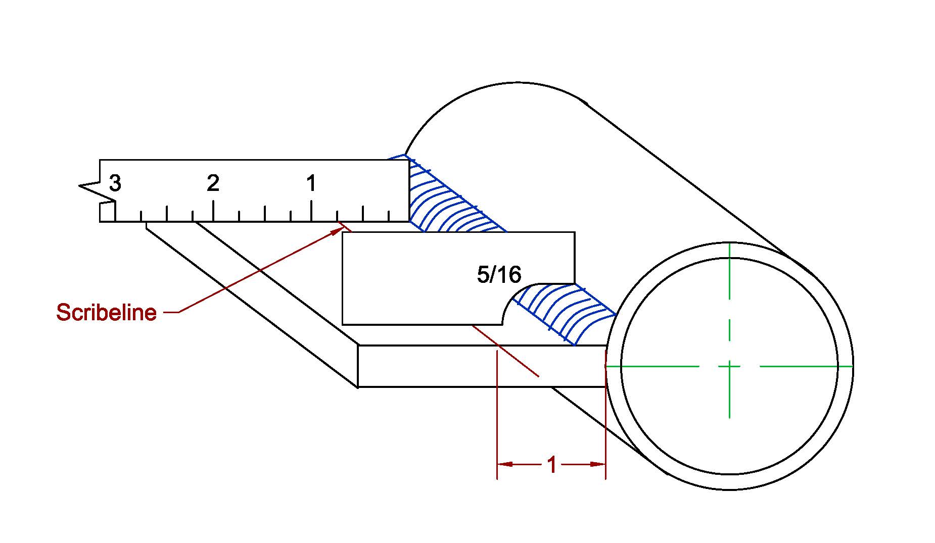
Working with the example provided by the preceding sketch, i.e., 3 inch schedule 40 pipe with 1/2 inch plate and a required fillet weld size equivalent to a 1/4 inch fillet weld:

If a scribe line is made on the flat plate 1-inch from the root, the fillet leg against the plate can be measured with a ruler. As measured from the scribe line, the dimension to the fillet toe should be less than 3/4 inch (requires a 1/4 inch weld leg).

Using the information developed from the sketch, the leg dimension on the pipe (in this case) could be measured with a 5/16 inch convex fillet weld gage.

No special gages required, but some forward thinking is a must.

As a TPI coming in to inspect the finished product: all is loss, the sky is falling, we're all going to die!

Best regards - Al
Parent - By thirdeye (***) Date 12-06-2014 13:15 Edited 12-06-2014 13:18
Al, Reference lines added at fit-up (and working from them) is a good idea, and one that escaped us.  Our first thought was a custom gage specific to this application, so that is still an option.... Hmmm, contest for the best design, winner decided by popular vote?
Up Topic Welding Industry / Inspection & Qualification / How To Measure Plate-To-Pipe Fillet Weld?

Powered by mwForum 2.29.2 © 1999-2013 Markus Wichitill