Not logged inAmerican Welding Society Forum
Forum AWS Website Help Search Login
Up Topic Welding Industry / General Welding Discussion / Brake Press Operation
- - By yojimbo (***) Date 03-16-2015 01:36
Advice or direction to instructions for a brake press operation needed.  A customer is needing 100 +/- custom brackets for a tenant improvement decking project.  The brackets are called out as bent not welded/fabricated.  Brackets will be built from 1/4" X 7" A36.  The bracket is a simple "Square Horseshoe" [my description], ie. it has 3 sides which I will call two legs and a web for lack of better/correct terminology.  The "legs" are to be 13" each and the "web" is of varying dimensions custom measured to fit in between the deck joists which are not symmetrical.  The majority of the brackets are 13" on all 3 sides but a large number of them are much narrower- down to 5". 

I have a few choices getting the bends done.  1] I can bring the material to a local machining shop and let them charge me for it.  2] I can buy bending tooling for the Scotsman Iron worker rated at 1/4" X 12" bending capacity which is an option I wouldn't mind spending on and have wanted this tool for awhile. 3] I can build any of the dozens of available DIY arbor press brake adaptations and do the bends in there.  The required tonnage is surprisingly [to me] small.  The machine shop guy I spoke with said 1/4" X 7" needed only 8 tons for a 90 degree bend, so really nothing.

Here's where my knowledge base fails:  Make a 90 degree bend [after calculating stretch out, material takeout from neutral axis, adjusting for spring back] and then turn the piece 180 degrees for the second bend-  How does one find the clearance for the material?  When the second bend is made it will be prevented from bending a full 90 degrees when the material hits the tooling [iron worker or arbor press] it's held in.  The machine shop guy mentioned "back bending".  Pride only allows me to ask so many questions of a man I am considering taking work away from so I just filed it away.  He said if that were allowed to "back bend" the narrowness of the brackets could be as little as 3"-5".  I gave this some thought and concluded their procedure would be to make the 1st 90 degree bend, turn the piece upside down and bend the center of the "web in the opposite direction which would allow the 2nd 90 degree bend to be made because the bend in the web would keep the material clear of the bender, and then flatten out the "back bend" to form a square "horse shoe" bracket with 2 90 degree bends.

The second bend in the "web" would form a sort of "W" [later flattened back out] but in so doing provide clearance for the 2nd 90 degree bend.

My hope is someone with some time on a brake can chime in and direct me to a textbook or online tutorial [I've searched without success] to let me know if I'm on the right track or missing it completely.  Aaevald here seems to contribute greatly to fabrication solutions needing answers, if he's not too busy to respond I'm betting he knows the answer already.

I should mention bend radius is not of great concern.  In their wisdom both the architect and engineer have left the design for the brackets up to the contractor.  Our field discussion decided a large bend radius in the corners where the joists meet the face plate is in our interest. The machine shop guy said they would produce a 1/4" inside radius and a 1/2" outside radius which would easily suit this job.

I've just finished a good sized contract with this contractor and PM, have is confidence and want to keep it so doing these brackets will be important.  Best news is there's plenty of money in the budget to get them done but just not much time so it's this weeks get it done schedule.

My thanks in advance.
Parent - By ctacker (****) Date 03-16-2015 01:46
I have done it the way you have described, back bending. making a bend in the center piece opposite of the two 90° bends just as you said.
Another option, if you can find one, is an eccentric die for the press brake. I don't think I've ever seen one do 13" sides with a 5" center.

I would be leery of making my own, there are a lot of forces involved. I once seen a guy lose half his face from an exploding home made piece in a press.
Parent - - By aevald (*****) Date 03-16-2015 14:42
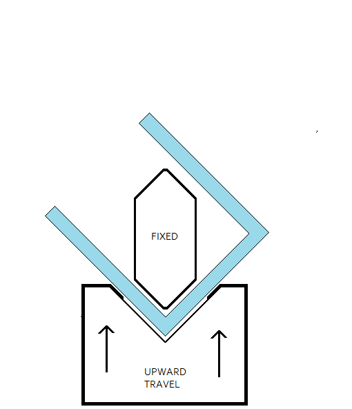
Hello yojimbo, here is a little "bender" that I built some time ago to do some of what I believe that you are doing. But, if you go a home-built route just be sure to keep everything in "overkill" mode. I have included the link to the thread in "Tricks of the Trade" where I included this some time back. Good luck and best regards, Allan

http://www.aws.org/cgi-bin/mwf/topic_show.pl?tid=13281
Parent - - By yojimbo (***) Date 03-16-2015 16:13
Allen,

Thank you for the reply and link to your bender.  Tell me if I am understanding this correctly:  You've positioned the bottom die [which moves] and cylinder under the piece to be bent and are using the upper die [stationary] above the piece to be bent.  Doing this so there is more room for clearance of the bent piece instead of having to clear a cylinder or bottle jack and/or the cross beam of an arbor press?  In your configuration the bent piece only needs to clear the width of the upper die?  Is that the general principle?  You mention a 1 3/4" minimum distance between legs being achievable.  If I am understanding that dimensional geometry your set up would be ideal for this project. I'd used the search function to find out what you had probably come up with in the past but the term "brake press" didn't show your tool.  Kind of figured you'd figured this out already.  I'll try bending to see what other solutions you've given us. 

Positioning the upper "knife blade" die above you've achieved more clearance space -hence narrower dimensions between legs- for the bending.  Correct?

I have approximately 200 bends to do in 1/4" X 7" A36 flat bar.  I would prefer to keep tooling expenses to a minimum.  If the tool were built for a one time production run would you think the dies would hold up if built from mild steel w/out hardening?  There is some 3/4" X 4" flat stock for the upper die I'd planned to put to use for the "knife blade" die and some gusseted 1/2" X 1 1/2" angle I'd planned to use as an inverted "W" welded to a 1/2" X 5" flat bar base plate.  Using that angle would give me a 2 1/8" opening on the Vee die which would seem to accommodate the "8X" opening rule I seem to keep coming across in what I am reading online.  Also on your "knife blade" die, what angle was machined into it?  The dies look very much like the brake press dies I've seen but I am guessing you fabricated/machined them yourself.

If you have time to respond I'd be grateful. 

Thanks.
Parent - By aevald (*****) Date 03-16-2015 17:53 Edited 03-16-2015 17:57
Hello yojimbo the top stationary "punch" is A2 tool steel in it's annealed condition, it was a piece of scrap from another project. The angles are 90 degrees included and it has a 3/32" flat where the 2/45 degree angles meet to avoid too sharp of a bend radius. The bottom die is 4140 annealed and the opening is 1 3/4", and I have not hardened either of the two pieces. The bottom die is machined @ 90 degrees and about 3/8" below the upper corners it is relief machined to an additional depth of 1/16". This can allow for bending beyond 90 degrees rather readily if needed.

To answer the question about clearance for bending: I chose this design for that very reason, it allows for bending of long legs on parts that would not otherwise be possible in a conventional Press Brake configuration.

I've got a sketch that I hope will shed some light on your questions and explain the set-up for the bender that I put together. Best regards, Allan

EDIT: if you look closely at the bottom die you will see the "recess" that is machined into the lower "V" this recess allows for bending beyond 90 degrees without needing excessive tonnage. Conventional punches/dies can achieve bends that are over 90 degrees even though the punch and die are both machined at 90 degrees, but this over-90 bending occurs at the very bottom of the punch/die configuration and requires a lot of additional tonnage.
Parent - - By aevald (*****) Date 03-16-2015 19:15
Hello again yojimbo, I just read one of ctacker's responses and he is certainly right about using due caution if you are making up a "bending unit".

In the one that I provided pictures of I have machined slots to allow for the use of shear lugs, these help to take the tonnage/stresses and to not rely on the bolts/screws to do so. I am also sure to not have myself or anyone else in the "plane of flying parts" should any bolts or shear lugs fail to do their job. Directly in front of and directly behind are the positions of safety. Off to the sides are where people should not be located in the interest of safety.

I use an air over hydraulic power source and a 15 ton ram on this unit. It makes for a very efficient and easy to operate unit and has been a part of a fabrication class that I teach. I have also used it in some of my fab shop stints during breaks from school. Mainly for making bends on roof access ladders where they transition from the ladder portion to the wider top portion. It's often a real pain to make those bends on the long pieces in a conventional press brake and much easier to make them on the floor with a portable bending unit turned on it's side. Best regards, Allan
Parent - - By yojimbo (***) Date 03-16-2015 20:59
Allen,

Thanks for getting back and attaching the sketch, it fills in and answers all my questions and concerns.  I agree with both you and Ctacker regarding strength of unit/safety concerns.  When a piece under tonnage fails the released stored energy equates to velocity/mass and momentum very very quickly.  Like most of us still around carrying more or less the same parts we were born with, I learned that through experience that only needed to be demonstrated once for the lesson to be learned.  Still review of lessons learned is simply wise precaution and both your reminders are taken into consideration.  Whenever I expect to try and duplicate tooling from either a specific manufactured unit or tooling built in shop I do my best to copy the member sizes and weights and generally feel safe doing so.  I don't have access to a machining center for this project [budget limitations] but your bending design and descriptions are the ticket.  I'll adapt it for my purposes and build it stout.  Thinking to put the porta-power unit to work on this using one of the shorter rams so the cylinder is located away from the bending unit.  Challenge there will be securing the ram to the device.  There is some 5/8" wall tubing around that should be about the right size  

Hydraulics are such a blast to work with as a shop aid and mistake fixer.  Several of my last projects require a lot of bending and rolling 1 1/2" sched. 40 for railings.  I bend with a Hossfeld and roll with a Bailiegh.  Both of those units have something of a learning curve on them to become proficient and accurate.  Adjusting slightly over bent or over rolled turns was a fun excersize  in employing the port-power and stops.  A guy can get almost as good fixing a mistake as making one.

Excellent design solution Allen.  Thanks for your help.

As always.
Parent - By aevald (*****) Date 03-16-2015 21:37 Edited 03-16-2015 21:49
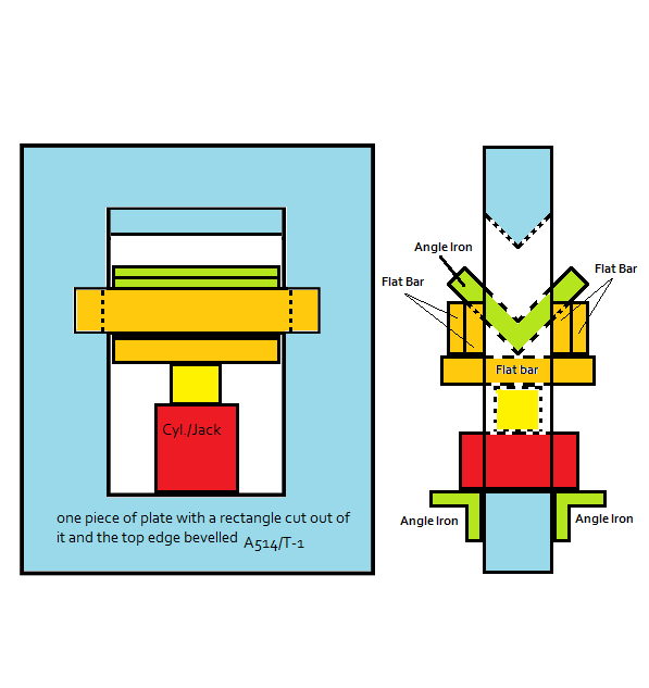
Here's an alternative that is simple and may very well address your needs: you can cut out the rectangle with radiused corners to increase strength/durability. and likely use 1" to 1 1/2" plate for the main frame and then size the other components as required. Good luck and please, if you can, share your results/experiences. Best regards, Allan

EDIT: I added a couple of angle iron pieces that could be added to the lower edge of the hole to aid with stability of the Jack or porta-power cylinder. You could weld the two ends and then weld the lower edge of the angle leaving the other edge to line up with the bottom edge of the hole and not apply any weld to keep it flat.
Parent - - By Jarhead1 (**) Date 03-16-2015 20:27
Hello Yojimbo,

If you can send me your email or if someone can teach me how to attach an excel spreadsheet I can send a good bending calculator.

Thanks
Parent - - By yojimbo (***) Date 03-16-2015 21:01
Jarhead-

Thanks for the offer.  I'll PM my email.

Jim
Parent - - By Stringer (***) Date 03-17-2015 00:35
Press brakes are everywhere these days it seems. Our guys do a w so good I can't tell the difference when they're done, just a little superficial line. We have offset punches, but usually just run a w with a regular punch. Not trying to dissuade you on a project, but it does sort of sound like a re-inventing the wheel kind of deal.
Parent - - By SCOTTN (***) Date 03-18-2015 14:44
If you can justify the cost for the Scotchman parts for this project, then you'll be able to use it for upcoming projects and eliminate the need for outsourcing in the future.
Parent - - By yojimbo (***) Date 03-19-2015 17:01
Scott,

I reviewed their line of press brake tooling for my 5014 model.  Cost is justified and as mentioned I've wanted to add it to the inventory but oddly when I spoke with the gentleman at Scottsman about a year ago re: the brake press attachment he really tried to steer me away from the purchase.  He indicated it was a less than optimal solution for bending and that the radii it produced were substandard.  None of the work I'd be using it for would be considered "precision" bending- +/- 1/6" is the closest I would need it to do so his "sales pitch" struck me as a funny approach.  My main concern with it is the set up time and that when it is set up the shear is out of commission.  I'll be talking with them again tomorrow to get more insight to make the decision.  All said however, the design with the fixed upper die and moving lower die on Allan's fabricated unit allows for a tighter dimension between bends- without back braking- than could be accomplished with any standard press brake or the ironworker attachment and a survey of the available remnants in shop tells me I could put one together for basically nothing more than my time which wont amount to much.  It would also be mobile and easily thrown on the back of the truck for site work which would be handy.  It's always fun to show up with a clever bit of fabricated tooling to provide a solution- sorta like Barnum's Bearded Lady- guys scratch their head and enjoy the gizmo's ingenuity.  Have you ever seen a carpenter's reaction the first time he saw a piece of pipe getting cut with a saddle bender?  Their eyes light up with wonder- same as mine did on my first helpers job.

Have you used the Scottsman brake press attachment?  I was looking at the 12" model that works off the sheer blade station.  What is your assessment?
Parent - - By SCOTTN (***) Date 03-19-2015 17:21
I've used it though it's been years ago.  It's not a bad little set up.  I don't know what the sales guy was referring to with the substandard radius.  I never had a problem with it.  I always follow the minimum radius for cold bending table that's in the AISC Manual of Steel Construction.  The problem I've always seen with a bend radius is that it's too tight, which makes the edges crack.  That's always been a problem with outside vendors supplying bent plates for structural applications.  They'll have a small die in the press brake for bending gage plates and then when they bend 1/4" plates, they don't change dies and the outside edges of the 1/4" plate cracks.  Despite reminding them about the problem, they continue to send bent plate with cracked edges and we continue to send them a bill for the labor to fix them.
Parent - - By aevald (*****) Date 03-19-2015 20:52
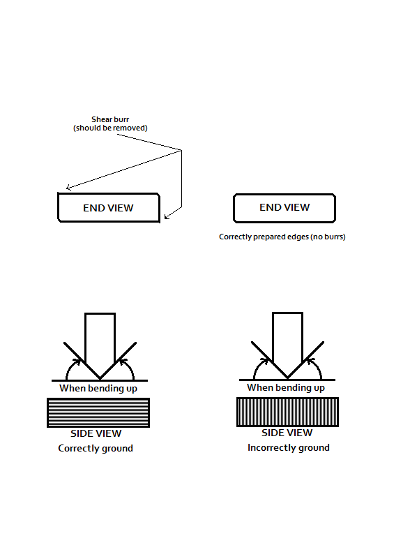
Hello Scott, to piggyback just a bit on your mention of "cracks" on the edges of bent plates. This generally occurs for a couple of other reasons besides just a minimum bend radius. Although you may already be aware of this, metal has grain (whenever possible or known, form across the grain), some metals are much more susceptible to cracking/breaking than others. Along with that, edge preparation has a lot to do with a lot of the cracking that is seen on formed parts. If you leave the shear burr on the edge of a part and the burr is facing away from the punch, there is a higher likelihood of seeing cracks(form a part that has been sheared and if the one edge that is facing up has a rounded edge and the other edge has the burr facing up, the side with the burr facing up won't crack and the other side might display some cracking).If you de-burr the edges of a part and grind horizontally across the edge(it doesn't present a "notching" effect) you will see less issues than if you grind 90 degrees to it(which does promote "notching"). I hope some of this makes sense. I'm going to attach a sketch that might explain this just a bit better. Best regards, Allan
Parent - - By SCOTTN (***) Date 03-20-2015 11:04
I understand.  Basically the same thing with weld test plates.  I've always been mindful of the grain when cutting weld test plates, and then when prepping the test coupons prior to bending, adding a  1/8" radius on the edges.
Parent - - By yojimbo (***) Date 03-27-2015 05:09
Brief update for any interested:  Couple of hours head scratching and sketching out a basic design- following Allan's general layout.  Gathering material from rack and container to stack it together and scratch my head some more then got on with it.  The premise was 1] a job specific tool to do close together bends <5" on 1/4" X 7" material with 13" legs. 2] tooling had to be cheap and what was available from the rack or minimum purchases from remnants at the suppliers. 3] accurate repeatable dimensions.

No tool steel here, it's all A36 and A 500 1/4" X 2" X 2" Sq. tube.  Drug out a piece of 3/4" X 2" bar, fixed it up to cut in the band saw and got a nice looking 10" long 90 degree included angle cut with 2 45 deg. slices.  Couple of swats with a sanding disk and some draw filing with a mill bastard and a right nice looking upper die was ready.  Two lengths of 3/8" X 1 1/2" Angle, toed down to form a "W" tacked up to a length of 1/2" X 5" bar and the bottom die was looking good.  90 deg. check on the bottom die showed more like a 93-95 deg. included angle but the reading I've been doing kept talking about the "8 times rule" and the dimension between the crown of the inverted angle was 2 1/8" so I'm figuring close enough. Everything stacked up and the Sq. tube gets tacked to the base, 20ton jack placed to get a good eyeball on locating the stationary top die, get it all tacked up, do some welding on the Sq. tube, don't put on the flat bar guides for the lower angle iron dies until I see if this thing is going to work.  Can't wait any longer and slice a 2" wide piece of 16Ga. in the shear and bend it up.  Too good to be true- no gauges or means to measure angle and spring back but yeah, perfect 90.  Up a notch.  Take a piece of 16Ga. X 6".  Bend 2 90s 3" apart.  great.  This thing is going to work.  It's not all the way welded out yet, but figure "go ahead.  push it a little".  1/4" X 2" bar in and start cranking [yeah, it a manual 20 ton, I mentioned cheap right?] and immediately notice this little piece of 1/4" doesn't move as easily as the 16 guage.  Stroke the upper die to the bottom of the lower angle die and it barely makes 90.  I know the spring back is gonna fail this.  It does.  back in and hit it again.  2nd time makes a 90.  I'd been reading about "coining" and air bending vs bottom bending.  Figure this is what they're talking about.  So decide to put it to a tougher test.  Grab a 1/4" X 4" rem of flat bar, put some lay out lines on to start figuring radii take outs [always understood it to be 1/2 material thickness, not so much here] and get to cranking.  Not so good.  About the time the piece is bottomed out in the lower angle die and still only maybe 80 degrees, [did I mention this contraption isn't even all welded out?  The lower angle iron dies are just well tacked] I start to hear sounds of begrudgement coming out of this inanimate object.  Give it a crank and there's a click, click ,click.  Another, and a little click, ping, ping.  I don't like the sound of this at all.  Anyone remember the movie "Das Boot"?  When they had to dive deeper than the WWII subs hull was rated for?  It was kind of like that with the image Stringer put in this thread about the guys face getting half chewed off when hydraulics met Immovable Object [not that my face couldn't use some rearrangement but I'd prefer maybe just a good dental plan or a shave].  Again, to get the 90 degree bend takes more than one bending attempt, sometimes 3 or 4.  And the clicking/pinging of steel pushed to it's limits doesn't make for a relaxing work enviroment. The jack is maxed.  When I release it I watch for what moves.  The bottom 1/2" plate the tubes are mounted give a tiny bit and when maxed it looks as though the 1/2" plate for the bottom dies is giving some flex as well.  Can't see light under a blade but it looks flexed.  Don't want to get into having to bend these hot.  The plan is to double up the 2, 1/2" plates with a doublers and some slot welds and see if that doesn't give it the "overkill" recommended in the first place.  Gotta say this though, properly built to withstand the required pressures the design will allow for very tight bends with no "back breaking".  As it stands now it will do 2 1/2" between bends on light material with long side legs and it's worth continuing the experiment before biting the bullet and sending the job out to a proper machine shop.  Had some fun today.  Further reports as things progress.  Thanks for the contributions so far.  Allan- it's a great solution you've provided, I want to see this work.  Also plan to try using 3/8" X 2" angle for the bottom die and increasing it's width.  Thinking that will require less force but not sure what it will do for radii. However it resolves, I already have an inexpensive, lightweight, portable bender I can always throw on the truck.  Think I'll wear the Goalie mask tomorrow in any case.
Parent - - By aevald (*****) Date 03-27-2015 06:21
yojimbo, please, please, please, be careful! I have a "slight" idea of what you have described, but, pictures please.

I believe that you might be undersize on the components, particularly when you go to a 7" width of the 1/4". The "mobile" bottom die needs to be stiffened more than you have allowed for at this point. The upper die will likely require additional stiffening as well. WELD, WELD, WELD, before you do any additional testing. and be sure to stay well clear of the line of fire if anything lets go. In other words, not above or beneath it, nor to either side of it. Directly in front will pose the least threat to your health.

20 tons of jack force might be a little bit under what's required as well, but that's the least part of an issue of what you have described thus far. Again, be careful and use plenty of caution. Best regards, Allan
Parent - - By Tommyjoking (****) Date 03-28-2015 02:34
I know I am real late on post but very interested....I have built supports before to run cinncinati dies outside the ram and bed to do just such work....width and thickness of piece matter a lot to keep from cracking a $$$$ factory die.  I have made a crap ton of homemade rigs to work with various ironworkers out of simple A36 steel and welded with S70 mig wire.    Not just for bending sheet metal clips but 3/8 material too......   A friend of mine built an 8ft "home made" press for bending steel and it was impressive in the fact he could do 1/4 steel up to 4' and get a even 90.   On lesser thicknesses it was wonder full and he cut out slots in the ram just for achieving parts like you describe.  I hope you pull it off and it works fine.....always be super cautious the first few bends....after standing on it till a pump is screaming one or two times you know it is not gonna fail on you in a bad way.
Parent - - By yojimbo (***) Date 03-29-2015 18:00
2nd Update.  Rebuilt in overkill mode.  Switched out base plate to 3/4" X 5 X 20" and Uprights to 3" X 3" x 5/16" Sq. Tube.  Upper stationary punch die is 1" X 3" X 10 1/2"" bar with 85 degree included angle.  Lower moving female die is 2 1/2" X 2 1/2" X 3/8" Angle mounted on 3/4" X 5" X 10 1/4" flat bar which has 1 1/2" X 3/8" flat stock welded to outside of angle legs and extend outside to center of uprights  to provide additional stiffness to angle and to act as guides for the lower moving die.  Opening of lower moving angle die is 3 1/16".  This wider opening allows for lower tonnage requirements but also increases radius of the bend which will still be within tolerance for this application- these brackets are going to be used for bracing the framing on some old balconies a contractor is rebuilding and way more than needed but the EOR wouldn't permit the use of Simpson brackets the contractor wanted to use.

After weld out started to test it.  Up to 1/4" X 4 1/2" flat stock the unit works well and easily.  Don't have any of the 1/4" X 7" flat bar the brackets will be made of so sheared a 7" length of the 1/4" X 4 1/2" flat stock and bent it.  It bent with effort and sure enough having no radius the sheared end started cracking.  Sheared and sanded a radius and the shears on another 7" length and bent it with no cracks.  On that second 7" piece that had a radius sanded into it I noticed two things, 1] it seemed to bend with slightly less effort [something to do with the cracking or simply there might always be variations of structure/properties in steel even in the same piece of material?] 2] I bent it more slowly, taking 3-4 seconds between strokes as it approached 90 degrees, thereby possibly giving it some time to "adapt" itself?  I do know the speed of the bend just as the speed of a piece in the section roller effect the outcome, so with some more playing around the "best" method may present itself.

There will be no problem with width on the bending- it's only restriction is the width of the upper punch die, so 3" inside and a 3 1/2" outside dimension with 13" legs is doable without back breaking and then flattening out the back bends.  The narrowest I need is 4" X 13".  No indication of undo stress, strain, give or the tweaking pings and creaks and unnerving sounds of impending disaster from first unit.  Eyes wide open of course and wits around but I will be able to do the project even if slower and with more effort than originally planned for.

Allan: Thanks for the concept and sketch/plans you provided.  You saved me a lot of head scratching and your design is effective.

Tommyjoking-  You have given me a great idea in your post.  After yesterdays fabrication of the unit and testing and realizing the results could be obtained but at the cost of substantial effort I went back to price the 12" brake press accessory for the 50514CM Scotsman Iron worker.  At $1400 and not able to provide the narrowest bends I need [ about 50 of the total 106 ] for this I'm not sure it's worth it.  But as suggested in your post: why not build a unit that will mount in the Iron worker and use the 50 tons of hydraulics available there for the wider 13' X 13" X 13" brackets?  If there's clearance of those, which I am going out to measure this morning it will be back to the head scratching to come up with something that might work there.

After all only amateurs borrow.  Professionals steal.

I'll get some pictures up when there's more time.
Parent - By Tommyjoking (****) Date 03-29-2015 19:36
On an Ironworker because of the tight spaces around the shear table I usually built these dies to run off the punch end.   Some Ironworkers have that dammable bolt on plate to the punch table with is usually insufficient support....so I would just make the bottom of the die self supporting strength wise and use those same bolt mounts...if they were deep enough and large enough.  If not use side plates to go down the frame and drill out for through bolting....especially if I had to get very far outside the frame to clear.  Where there is a will there is usually a way to make it go with what you have.   Some have the angle shear located just right to accept a die that can extend past the frame in such a way to make a tight u bend.   Gussets....heavy gussets for that scenario.
Parent - By aevald (*****) Date 03-29-2015 20:50
Hello again yojimbo, glad to hear of the "rebuild" to a more robust design. Also glad to hear that you are on your way to successful production on your project. Would definitely like to see some pictures.

As to possible speed increases in your design, an air-over-hydraulic unit, whether that be in the form of a porta-power or an air-over-hydraulic jack, that might be a reasonable answer. Stay safe and good luck on the project. Best regards, Allan
Parent - - By MachineMfg Date 04-24-2018 09:28 Edited 09-24-2018 04:16
Recently I wrote one article to fully explain things about press brake, hope it can help the audience: https://machinemfg.com/press-brake-ultimate-guide
Parent - - By UDresner Date 04-24-2018 20:28
Please check your link, because it seems to be broken somehow
Parent - By MachineMfg Date 09-24-2018 04:17
hi, the link has been updated to the correct one.
Up Topic Welding Industry / General Welding Discussion / Brake Press Operation

Powered by mwForum 2.29.2 © 1999-2013 Markus Wichitill