Not logged inAmerican Welding Society Forum
Forum AWS Website Help Search Login
Up Topic Welding Industry / General Welding Discussion / WPS Tolerances
- - By TALower (*) Date 04-23-2021 08:26
This question is about writing a prequalified WPS based on manufacturer’s recommended parameters to the requirements of AWS D1.1 (2020) Table 5.2 using FCAW-G process with 0.045” electrode and M21 compliant shielding gas (82% Argon and 18% CO2).

The manufacturer states on the data sheet that for the 1F & 1G positions, the parameters should be
Root pass volts =   19 to 20
Root pass amps = 150 to 180

Fill pass volts =     25 to 28
Fill pass amps =    240 to 300

From one standpoint, I should be able to apply the tolerances to the manufacturer’s values and have the following on my WPS:
Root pass volts (+/-15%) =.   19 (16.2 to 21.8) to   20 (17.0 to 23.0)
Root pass amps (+/-10%) = 150 (135 to 165)   to  180 (162 to 198)
Fill pass volts (+/-15%) =      25 (21.2 to 28.7) to    28 (23.8 to 32.2)
Fill pass amps (+/-10%) =   240 (216 to 264)   to  300  (270 to 330)

From another standpoint, any tolerance stated must be within the range listed on the manufacturer’s data sheet:
Root pass volts (+/-15%) =.   19 to 20 (the only option is 19.5 (16.6 to 22.4))
Root pass amps (+/-10%) = 150 to 180 (the only option is 165 (148.5 to 181.5))
Fill pass volts (+/-15%) =      25 to 28 (the only option is 26.5 (22.5 to 30.4))
Fill pass amps (+/-10%) =   240 to 300 (the only option is 270 (243 to 297))

As you can see by the values in the second group, even when specifying the exact middle of the manufacturer’s ranges, the allowable tolerance will put you outside of the manufacturer’s range, which then requires a qualified WPS.

So what am I allowed to put on my WPS parameter table? Only a single set of values which a reviewing CWI could reject because the tolerances allow the welder to be “outside parameters”? Or the range of values as recommended by the manufacturer which a reviewing CWI could reject because the tolerances allow the welder to weld outside of parameters?

If I were to run a PQR with this gas and wire and tightly controlled 19 volts and 165 amps, I would be allowed to specify tolerances. Why shouldn’t I be allowed to specify the manufacturer’s ranges with tolerances?

As an example, let’s use the recommended root pass parameters: I am not saying that the welder is allowed to set his machine to 16 volts and use a wire speed that will achieve 135 amps, and then go an additional 15% and 10% below those values while welding .

I am saying that the welder should be allowed to set his machine to 19 volts and use a wire speed that will achieve 150 amps without being told he will be outside of the allowed tolerances while he welds.

If the code is interpreted so strictly that welding becomes impossible, the code is being interpreted wrong.
Parent - - By Lawrence (*****) Date 04-23-2021 16:22
Interesting.

1st.   Code isn't "interpreted"   It ought to be clearly read and followed.  I know its mincing words... But if there are grey areas that need interpretation, that's a part of code that isn't doing its job well enough.  Users should not be forced to interpret.

2nd.   135 Amps for an FCAW root pass?    That is extremely low whether the manufacturer allows it or not.    135 amps would be low for a short circuit open root, and if you are doing open roots, prequalified procedures don't apply anyhow.    Spray and Globular are the prequalified transfer modes you might see with FCAW... You are not getting Globular or Spray with 135 or even 150 with M21 gas at any voltage.  with .045 you are going to be at around 200 amps and maybe North of that to get a prequalified transfer mode I would think.

The manufacturers recommended currents/WFS and voltage may be used to weld together deck chairs eh?  That does not necessarily mean they will work with AWS D1.1 prequalified WPSs.    Not every parameter set within the manufacturers recommendations will be compliant with a prequalified WPS in every case.

The nice thing about gas shielded FCAW is that you can get great all position welding with a very small parameter range in any position and on unlimited thickness...  Meaning 230-260 amps and 25-27 volts will weld 10ga to unlimited thickness in any position with .045.  You could easily go higher.

Why not have the welders tell you.. or better yet, demonstrate how parameters set at the HIGH end of the Manufacturers suggestions can be used for everything, then generate the WPS that makes the welder happy and complies with code and is within the manufacturers range.
Parent - - By 803056 (*****) Date 04-23-2021 21:06 Edited 04-23-2021 21:27
I use a graphical presentation of the welding parameters using the data provided by the manufacturer.

If one tries to apply the "tolerances" permitted by D1.1 to each parameter individually, the welder isn't likely to be happy. As one parameter is increased, it is likely the other parameter will have to be increased as well.

The graphical approach shows the welder how much to increase the voltage if the wire feed is increased, or how much the voltage should be decreased if the wire feed is decreased. Likewise, many FCAW electrode work best if the electrode extension is increased if the WFS and voltage are increased and the electrode extension is often reduced if the WFS and voltage are decreased.

The parameters recommended by one manufacture for their particular electrode is unlikely to be optimum if the electrode from a different manufacturer is substituted.

As mentioned by Lawrence, it is a good practice to run a few beads to feel out what range works for the application, i.e., thickness or position, groove or fillet.

I plot the parameters on a graph and tell the welder to start at the midpoint of the wire feed, then the voltage, check his CTOD (includes the arc length in contrast to electrode extension that doesn't include the arc length). The amperage is a quick check that everything is in balance. He can adjust the parameters higher or lower as long as he is within the ranges indicated by the graph. The attached graph is not specific to D1.1, it is just an example of how I present the data. There is some information missing, such the specific brand and diameter, but you can't expect me to give away all my secretes.

Just saying - Al
Parent - By TALower (*) Date 04-26-2021 08:25
Al,

Several years ago, I saw in Inspection Trends a parameter graph much like the one you shared. It might even have been your’s, I don’t remember who the author was. I incorporated it into my procedures and shared it with the shops I work with. Management seemed ambivalent, welding supervisors the same, but many seasoned welders and especially new welders found it very helpful and easier to understand. It was very satisfying to tell the welder, “Anywhere on that line is acceptable” and they would UNDERSTAND.

However, the lack of acceptance/understanding from reviewing CWIs and Engineers forced me to revert back to a standard parameter table. In my business, I often find myself editing procedures based on the reviewer’s wants, rather than the needs of the people who actually use them.

I agree with your statement that the parameters of one electrode do not necessarily work for all. That is why my procedures are unique to each electrode. My procedure format makes it fairly simple to make those edits, plus when the project requires D1.8 compliance, the make and model of the wire are already included.

Finally, yes, it is good practice to run a few beads. That is why we have tolerances. The procedures set the parameters and tolerances and the welder practices a bit and finds what he is comfortable with inside the parameters, and we are off and running.

But, like I said in my reply to Lawrence: you didn’t answer my specific question.
Parent - - By TALower (*) Date 04-26-2021 07:54 Edited 04-26-2021 08:27
I disagree with your first statement. Code is “interpreted”, otherwise you would not have some users who argue that the code says one thing, while others argue that the code says another, and both back their statements up with references to the code. I would guess that even in the committees, you have disagreement over what the code does and does not say, and those members are far smarter than I will ever be when it comes to code “interpretation”. I agree with another statement, “Users should not be forced to interpret.” I truly wish that the code was easily understood such that I did not have to visit this forum.

Your 2nd point, while potentially valid in some cases, is irrelevant to my question. You may feel it is very low, but the manufacturer (hopefully I will be able to attach the actual page) states that the parameters are acceptable. I do not have the facilities necessary to perform the same tests they do so I must take their word for it that they are in compliance with the requirements of AWS D1.1.

However, neither you nor Al answered my question: Am I allowed per AWS D1.1 (2020) Table 5.2 to specify the top and bottom of the manufacturer’s recommended parameters and have my tolerances extend above or below those? Or must I specify a tighter range such that my tolerances keep the welder inside the manufacturer’s range?
Parent - By Lawrence (*****) Date 04-26-2021 14:16 Edited 04-26-2021 14:43
Specifically.   "Am I allowed per AWS D1.1 (2020) Table 5.2 to specify the top and bottom of the manufacturer’s recommended parameters and have my tolerances extend above or below those? "     No.   

Looking at 2020 edition:   Table 5.1  Notes "Maximum Current" as the only value that must be within the Manufacturers limit.  Maximum Current..  Nothing else, nowhere else, no other parameter.   There is ZERO "Interpretation" here, there is only an understanding of what the text actually says.   "Shop Talk" is the typical bug-a-bo here; meaning that someone once once said "Prequalified parameters must be in the Manufacturers ranges"   But where does the code call that out?   That's not an interpretation issue.  It's an assumption issue.  One which has caught me dozens of times.  We think we know something.

Table 5.2  Lists the essential variables and the ranges that apply for prequalified WPS's for Current, voltage, travel speed, etc.   ...  When I write a prequalified WPS.. I pick a value and consider the percentage + & - and see what I would like to put into my WPS to be most helpful to the welders..   I cannot go beyond the percentages listed in the table high or low.   The only place the Manufacturers recommendations come into play would be for the high current value.

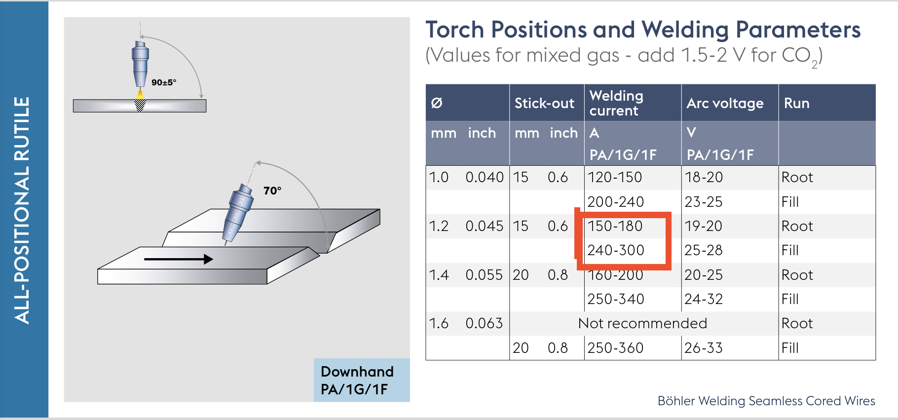
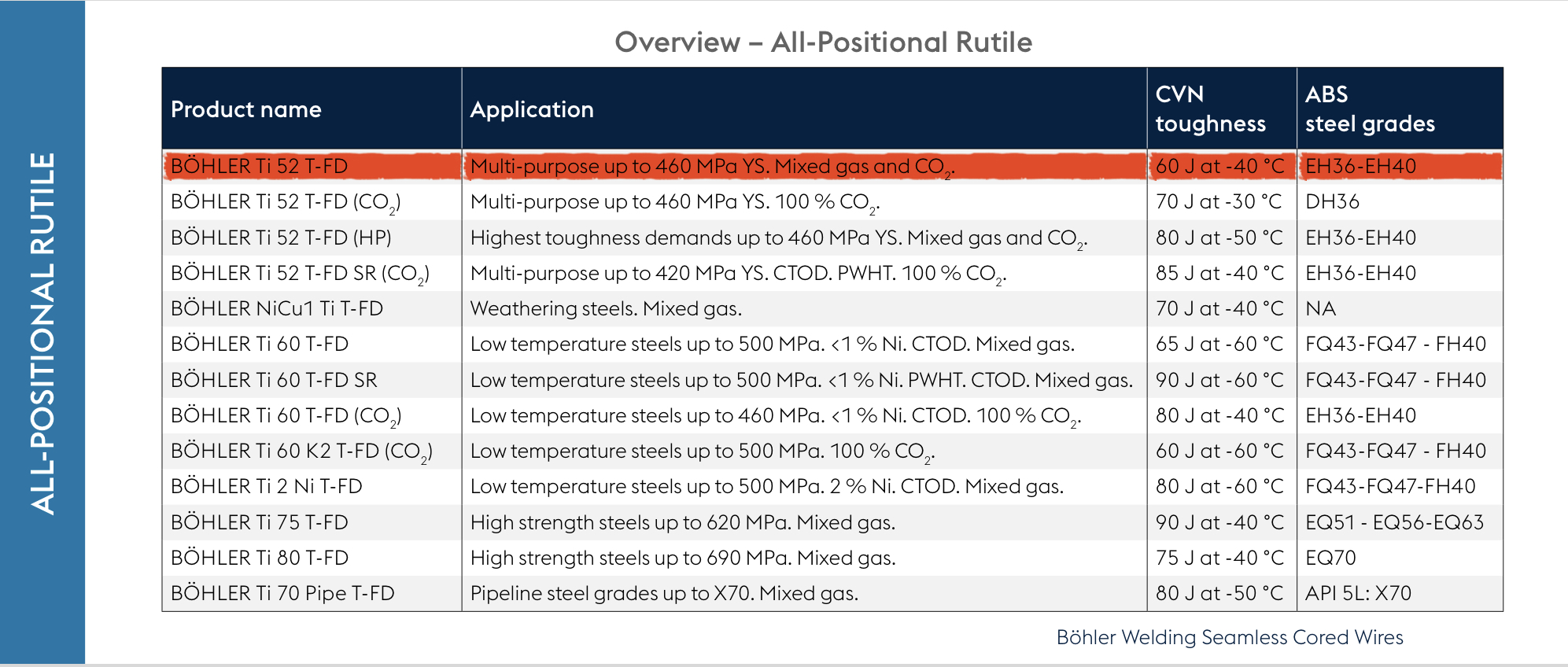
As far as the super good data sheets you attached...  Remember this:   They are published for EVERYONE who uses them, not just D1.1 code users.   Again;  You can use that FCAW electrode wire on 16gage sheet right?  You might need that 150 amp and low voltage recommendation to get the weld, and it would be short circuiting... But that would never work in a D1.1 application, it's the wrong transfer mode and on material thicknesses used in the code, would be insufficient to comply.    There is not a thing wrong with the manufacturers data sheets,  but you must recognize they have a scope that may exceed the code for purpose.

So there are two things going on here (or at least I would like for there to be)
1)  Understanding code compliance
2)  Helping you generate a good, workable, prequalified WPS that is compliant.

Nuts and bolts...  Assuming a CJP V-groove with backing that is prequalified in D1.1.      A root pass with .045 FCAW and M21 gas can be easily placed at 220-290 amps...  I can think of absolutely no reason to run at 150 amps unless you are repairing a 10gage edge.   

For fillets, even 10ga to 10 gage,  That .045 FCAW can run at least 230-260 amps with no burn thru...  So both grooves and fillets can be placed (in all positions) without overheating anything and stay in a tight range.

It would be super helpful if you gave us some information about the actual joints you are making.

Generating a WPS with gigantic current ranges is not particularly helpful to welders unless they are high level experts who have a great understanding of process control.  It leaves the door open to variable combinations that might not make good welds.   The tight parameter approach is much more favorable, especially in structural manufacturing.  This goes for both quality and productivity.
Up Topic Welding Industry / General Welding Discussion / WPS Tolerances

Powered by mwForum 2.29.2 © 1999-2013 Markus Wichitill