 By 803056
  Date
Date 10-15-2009 21:15
Edited 10-16-2009 03:08
The inspector is tasked with monitoring the welder during production to ensure the welder is working within the parameters of the WPS, including any heat input limitations. The parameters were established when the test piece was welded and the test results verified the process produced the required mechanical properties, including the required notch toughness. The welder's parameters will vary as the test plate is welded unless the process is mechanized. For that reason, I use statistical analysis to derive the median values for voltage, amperage, travel speed, wire feed speed, and heat input.
The welder should be instructed how he is to weld and any constrains imposed by the need to limit the heat input while welding. Few welders appreciate the need to limit heat input unless they have received some instruction about heat input and its affect on the mechanical properties of the weld and heat affected zone. They also need instruction on how to monitor and control heat input.
The inspector likewise needs to understand the importance of limiting heat input and how to monitor it during welding operations. While I don't totally disagree with 3.2's position regarding the damage done if the welder exceeds the heat input limitations on one or two weld beads in a groove that requires many passes to complete, but the code is what it is and the values established by the PQR/WPS apply to each weld bead.
Codes define the limits for heat input and each code or welding standard addresses it a little differently, but the desired outcome is the same. The primary goal is to limit the heat input to maintain the mechanical properties and to limit grain size to enhance notch toughness or to minimize the degradation of the properties in the HAZ or weld. Some welding standards simply state the maximum heat input permitted. Others have the fabricator determine the maximum heat input by "trial and error", i.e., a procedure is qualified and if it passes, those parameters used are the basis of establishing the ranges of the welding parameters.
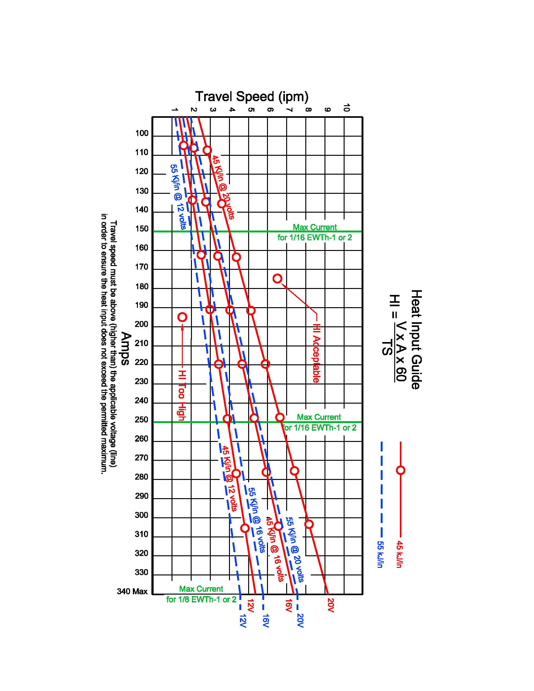
A properly written WPS can provide the welder with much needed information if it is presented in a manner that is easily understood. I find that a graphical presentation is the easiest to decipher and provides a relatively easy means of monitoring the welding parameters so some predetermined limit on heat input is not exceeded.
The trick is to balance the voltage, amperage (wire feed speed), and travel speed. For the semi-automatic welding processes the wire feed speed is constant once it is dialed in. Likewise, the voltage is a constant (hence the term constant potential power supply). Amperage will vary if the electrode extension isn’t defined, so define it! The only real variable is the travel speed. The graphic presentation can use the travel speed for the vertical axis and amperage or wire feed speed as the horizontal axis. Voltage can be presented as several “horizontal” plot lines, each with a specific voltage value.
Processes that use constant current power supplies can be presented in a similar manner. The attached sketch may clarify the manner in which I present the data.
You can also present the data using a “Triangular” presentation where voltage, amperage, and travel speed are plotted to create a “window”, but it takes time to construct and the axis are not linear.
Tables can be difficult to use. The simple graphic presentation is what I find to be easiest to construct and easiest for both the welder and inspector to use.
It isn't rocket science. If it was, I would have to find a different line of work.
Best regards – Al


