Not logged inAmerican Welding Society Forum
Forum AWS Website Help Search Login
Up Topic Welding Industry / Technical Discussions / Spray arc .023 wire and why is it "wrong" ?
1 2 3 Previous Next  
Parent - - By electrode (***) Date 11-01-2014 15:12
46.00,
with respect to 'blocking action' I shall hope, just temporarily.
Oh ... I suspect that I need to cut down on my 'walls' now! :)
Parent - - By 46.00 (****) Date 11-01-2014 15:27
No your OK! I enjoy your input!
Parent - By electrode (***) Date 11-01-2014 15:42
I appreciate this.
And ... before I forget - ditto.
Parent - - By Lawrence (*****) Date 10-31-2014 23:10 Edited 10-31-2014 23:23
With all due respect;  the current, voltage and gas are different in each example.

How can pictures with not even the slightest relationship in controls inform us of anything at all?

Is there a conclusion, theory or story related to GMAW arc behavior these images and data are supposed to tell us?

What am I missin?

Edit:
Also, for what it's worth;  when a man knows he has done wrong to somebody, it is healthy to admit it, tell the offended party that you will purpose never to wrong them again, and only then,Ask for forgiveness.

In my opinion this is what an apology is. Anything less is not an apology. Anything less is worthless. Anything less says loud and clear that you don't really care to anybody with even a small amount of wisdom.

Not every misstep merits an apology, but good long lasting relationships need such things whether they are personal or professional in my opinion.
Parent - - By 46.00 (****) Date 11-01-2014 00:25 Edited 11-01-2014 00:29
I guess my comment on saying sorry has transposed to various threads? Are you sorry for that?
Parent - - By Lawrence (*****) Date 11-01-2014 13:30
It's a good conversation !
Parent - By 46.00 (****) Date 11-03-2014 13:54
true!
Parent - - By electrode (***) Date 11-01-2014 10:59
Lawrence,
likewise with all due respect.

1. I have succeeded in reflating this discussion - good, in my opinion.
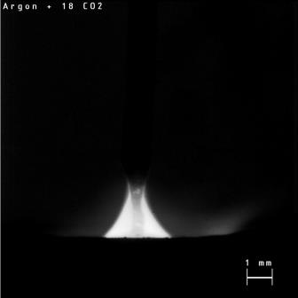
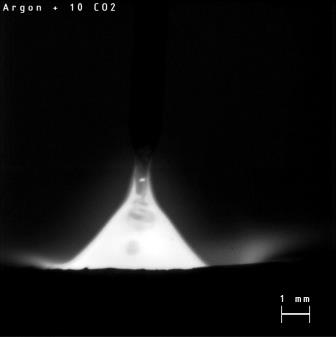
2. I partially agree with what you say when talking about the 'pictures' themselves without being related to anything further. This is pointing toward the lively debate we recently had along with another thread. That, however, is untrue in this case. On the contrary; the pictures (of course singular 'snapshots' in time only) are representing specific welding conditions (#1; #2; #3) and were related to specific parameters. What I personally can see from that again is; the voltage (within the experimental error) is the same. Voltage scatter of ± 0.1 V should be considered within the experimental error. I hope you can agree with me on that. I, however, appreciate that you have been willing to notice that at least that the current is varying. Of course, if voltage + all peripheral conditions are constant, current should become the output variable.

But, and that is the reason why I did spend my time for preparing the images and embedding them here; we have spoken about "crackling", "whooshing" and even "buried" spray arcs, didn't we, Sir? And, we had discussed about "arc length", "short" and "long" arcs. Then we have reasoned about "crackling" or "whooshing" and I think it is exactly here, where we become distinct to each other - which is good of course. While you say e.g. "mill scale", which is valuable, as I was already admitting formerly, as being part of something that we haven't fully discovered yet in this thread, something in me is being switched on for considering "mill scale" from a physical, or maybe chemical, standpoint. So, I was agreeing, that "mill scale" may have an impact on what can be observed under specific experimental conditions (eloquently described by yourself), but I was disagreeing that "mill scale" generally serves as the root cause for "crackling" or "whooshing" (note qualitative terms) spray arcs. Please do not get me wrong, when considering this from a more philosophical perspective. That reminds me a little of 'Knowing-that' and 'Knowing-how'. 'Knowing-how' is always aware of 'Knowing-that' but not compulsorily vice versa.

I wish to tie in here.
All this, and certainly more, in mind; I can see 3 different 'arc pictures', taken from high-speed video images, obviously showing different "arc lengths" (whatever that actually means) based however on the same voltage. And all this, although everyone (if memory serves me correctly, including yourself) apparently relates "arc length" to 'voltage'.

That particularly was the reason for me to share these images. How, so my question, can all three arcs have the same voltage but nonetheless can be different in their 'length'? Or ... was it even that all 3 arcs were having the 'same' "arc length" finally and #1 was only buried underneath the workpiece surface? Was it then the case, that this difference has led to some proportional increase in fusion depth, maybe? I can see many things. I can see questions upon questions.

So, what am I missing?

And further. I wish to quote Henry here - and btw I wish to thank him for his valuable contribution/observation:

"And I ask you this because the reference measurement of 1mm in the image shows that the size of the arc plasma streams vary in size. There is also from what I see a variation in the height distances from the weld pool to the location within the plasma stream on the electrode "cylinder" where the "lorentz" and other forces also start creating a pinch effect @ the electrode cylinder... So please tell me that my eyes aren't playing tricks with my powers of observation..."

CTWD has been constant throughout as also stated in the 'experimental parameter set up'.

To come to an end - for now.
In your opinion and, as initially stated, asked with all due respect. Was there one gas metal spray arc among those depicted ones which might have been classified "buried"?

PS: I ask your understanding for not replying on your lesson in "correct excuses".
Parent - - By Lawrence (*****) Date 11-01-2014 13:27
No buried arcs in your pics :)

A buried arc wod be what it says it is:  burried.  Meaning an arc that occurs below the base metal surface.

There will be more commentary friend Electrode, when I'm not posting with my phone :)
Parent - By electrode (***) Date 11-01-2014 13:32
Lawrence,
thank you.
I'll have to admit - greatly I do enjoy discussing with you et al. :)
Parent - - By PlasmaHead2 (***) Date 11-01-2014 16:45
Electrode,
All I can do at this point is sit back and learn.
It's your can of worms now :wink::lol:

Oh and I'll add this; from the descriptions of buried arc that I've read about none of your pictures are buried arc. You would not see any arc cone and the wire would be going straight into the puddle with the arc being somewhat below the surface.
Parent - - By electrode (***) Date 11-01-2014 17:22
PlasmaHead2,
I do gratefully acknowledge both your friendly 'relinquishment' and your quite reasonable 'buried arc' estimation.
With regard to the former, however, kindly be asked to provide further input similar to the latter.
I would even dare to say - we neither have reached nor crossed the finish line in this marvellous subject. :)
Parent - - By PlasmaHead2 (***) Date 11-01-2014 19:56
The finish line is Far far away... :lol:
A picture is worth a 1000 words so this quickie paint sketch might be worth 100-200...
The top of the sketch is what I remember seeing in description of buried arc, the bottom would be some version of a spray arc.
Parent - By electrode (***) Date 11-02-2014 08:45
Thank you for the additional visualisation, PlasmaHead2.
Parent - - By ssbn727 (*****) Date 11-01-2014 21:54 Edited 11-01-2014 23:26
So now you want to pursue the infamous Buried arc again? Okay. let's see what I can come up with...

This book is written by Larry Jeffus and Lawrence Bower (sound Familiar?:grin:) and is titled: "Welding Skills, Processes and Practices for Entry-Level Welders:, Book 2" in the book starting at the bottom of page 9 and continuing through page 10 and I must apologize Larry and Lawrence but I don't have the book personally so I couldn't tell you if the topic of "Buried arc transfer" extends beyond page 10 although if I were to guess, I would say that it does... Here's the link to the book:

http://books.google.com/books?id=EATxJaxrls4C&pg=PA9&lpg=PA9&dq=buried+arc+transfer&source=bl&ots=lgHtAID9Sr&sig=m0A9vu0sDJmH0jz_51iyRx1CwF4&hl=en&sa=X&ei=XTtVVJebLsmuyATtt4LwCw&ved=0CEcQ6AEwBg#v=onepage&q=buried%20arc%20transfer&f=false

Here's the short definition of buried arc transfer from the student resources glossary according to Cengage: "In gas metal arc welding, a method of transfer in which the wire tip is driven below the surface of the weld pool due to the force of the carbon dioxide shielding gas. The shorter arc reduces the size of the drop, and any spatter is trapped in the cavity produced by the arc." Here's the link:

http://www.cengage.com/cgi-wadsworth/course_products_wp.pl?fid=M35&product_isbn_issn=1111039178&chapter_number=10&resource_id=10&altname=Glossary 

This article is from the Fabricator:

"Globular transfer means the weld metal transfers across the arc in large droplets, usually larger than the diameter of the electrode being used. This mode of transfer ­generally is used on carbon steel only and uses 100 percent CO2 shielding gas. The method typically is used to weld in the flat and horizontal positions because the droplet size is large and would be more difficult to control if used in the vertical and overhead positions compared to the short-circuit arc transfer. This mode generates the most spatter; however, when higher currents are used with CO2 shielding and a buried arc, spatter can be greatly reduced. You must use caution with a buried arc because this can result in excessive reinforcement if travel speed isn't controlled."

http://www.thefabricator.com/article/consumables/understanding-transfer-modes-for-gmaw

This article I believe Lawrence recognizes the author being Jack R. Barckhoff... It was published in the "Welding Design & Fabrication" Magazine in the October issue of 1986...
The title of the article is: "Smart Managers Reduce Arc Time" and the topic of buried arc transfer can be found in the second page of this relatively short article - link: 

http://www.barckhoffweldingmanagement.com/articles/smart_managers_reduce_arc_time.pdf

This article focuses on real time application of buried arc transfer and can be found in The Lincoln Electric web site as one of the application stories... This article writes about a pipe mill that was striving to become the most efficient as possible to produce "36" diameter, 0.820" (20.8 mm) thick API 5L Grade X70 produced in 40-foot nominal lengths.  The 40 foot long sheet is formed into a tube by Berg's Tri-Roll Bender... Once the plate is formed into the proper tubular shape, the longitudinal weld is completed in three passes, beginning with a continuous tack weld. For the Gulfstream Project, the longitudinal welding procedures were qualified to both ASME Section IX and Berg's internal standards."

"In 1999, Berg had a single, DC 1500 power source. For every diameter change in pipe, the system would require 45 minutes to change out the cage that positioned the plate edges for welding. To eliminate this, Berg turned to the expertise of The Lincoln Electric Company. Because of a long, 21-year relationship with Lincoln, Berg looks to the company for innovative solutions to welding challenges and ways to provide higher productivity in its welding operations. At Lincoln's suggestion, Berg installed a continuous tack welding system utilizing two, DC 1000 power sources and a NA-5 control. This new, CNC-controlled tack welder has hydraulic cylinders, which automatically reposition themselves when the pipe diameter changes. This system has reduced changeover time to approximately five minutes. This new system has also eliminated some of the problems with closing the bevel for welding that Berg Pipe was experiencing with its former system.

These two DC 1000s create a continuous seam tack using an open arc gas-metal arc welding (GMAW) process at high speeds of 260 inches per minute. Commonly referred to as "buried arc", this process is characterized by low voltage, short arc length, and very high travel speeds allowing for a deep penetrating weld at reduced heat inputs.

During tack welding, hydraulic rollers on the system hold the pipe seam together. A laser guidance system from Uhrhan & Schwill is also used to guide the arc in the weld groove and maintain radial alignment of the plate edges. Because this laser guidance was not present on the old tack welding system, it eliminates the time that was needed previously for the operator to stop the weld and adjust these items manually.

While some competitors use intermittent tack welds, Berg Steel Pipe Corporation feels there are benefits to a continuous seam technique to close the formed pipe cylinder for welding. "Intermittent tack welds require the use of a backing flux or a copper backing bar during subsequent submerged arc welding, while ours does not," noted Fred Hafner, PE, Chief Metallurgist/QA Manager for Berg Steel Pipe Corporation. "This means that we achieve higher productivity since the backing provided by the continuous seam provides the attributes for fast travel speeds and deep penetration in ID welding."

Using a buried arc process allows for the elimination of weld spatter typical of globular transfer because the arc is "buried" in the weld puddle. This process also requires only a CO2 shielding gas, eliminating the need for more expensive argon gas. For the tack welding of 0.820" thick pipe, Berg Steel Pipe Corporation uses Lincoln L-50 5/32" diameter wire electrode at 1,500 amps.

Since installing the new system, Berg has been extremely pleased with the results. "Our tacking system is very reliable and helped relieve the problem of the arc outage we were experiencing," said Burton. "We also employ the use of CNC controls which can store data on a particular wall thickness so that we can provide rapid changeovers by simply calling up previously-stored information." " here's the link to the entire application story:

http://www.lincolnelectric.com/en-us/support/application-stories/Pages/berg-steel-pipe.aspx

An interesting article as well to read which is why I edited this post to include it with the rest of the articles and papers:
REVIEW: High speed fusion weld bead defects T. C. Nguyen1, D. C. Weckman*2, D. A. Johnson2 and H. W. Kerr1
* = Corresponding author, email dweckman@uwaterloo.ca, 
1 = School of Engineering and Information Technology, Conestoga College, 299 Doon Valley Dr., Kitchener, Ontario N2G 4M4, Canada
2 = Department of Mechanical Engineering, University of Waterloo, Waterloo,Ontario N2L 3G1, Canada
"A comprehensive survey of high speed weld bead defects is presented with strong emphasis on the formation of humping and undercutting in autogenous and non-autogenous fusion welding processes. Blowhole and overlap weld defects are also discussed. Although experimental results from previous studies are informative, they do not always reveal the physical mechanisms responsible for the formation of these high speed weld bead defects. In addition, these experimental results do not reveal the complex relationships between welding process parameters and the onset of high speed weld bead defects. Various phenomenological models of humping and undercutting have been proposed that were based on observations of events in different regions within the weld pool or the final weld bead profile. The ability of these models to predict the onset of humping or  undercutting has not been satisfactorily demonstrated. Furthermore, the proposed formation mechanisms of these high speed weld bead defects are still being questioned. Recent welding techniques and processes have, however, been shown to be very effective in suppressing humping and undercutting by slowing the backward flow of molten metal in the weld pool. This backward flow of molten weld metal may be the principal physical phenomenon responsible for the formation of humping and undercutting during high speed fusion welding."

In GMAW with CO2 shielding gas, the buried arc technique has been reported as an effective means of achieving higher welding speeds and filler metal deposition rates.5,10 With this technique, the arc is actually located beneath the original surface of the work piece during welding. This reduces the weld spatter and increases the metal deposition rate. In addition, the overall arc pressure may be reduced since the cathode is located within the weld pool crater.20 This is consistent with the arc pressure and supercritical models wherein a reduction in arc pressure is predicted to decrease the arc gouging directly under the arc, thereby suppressing the formation of humps and undercuts to higher welding speeds and allowing improvements in productivity.4

https://uwaterloo.ca/centre-advanced-materials-joining/sites/ca.centre-advanced-materials-joining/files/uploads/files/2006_review_high_speed_fusion_weld_bead_defects.pdf

I'm going to stop here with respect to the buried arc transfer and switch gears to present an investigation that was done back in 2006 @ The Ohio State University Welding
Engineering Laboratory at the Edison Joining Technology Center... The investigation is titled: "INVESTIGATION OF THE EFFECT OF PULSING SHIELDING GAS IN ARC WELDING"
It's an interesting investigation nonetheless... The Abstract starts with this:

"Russian engineers have discovered a new method of delivering shielding gas for arc welding. This new method uses equipment known as the Gas PulserTM to deliver an alternating or “pulsing” supply of two pure shielding gases which are input, creating an alternating supply of shielding gas delivered through a single gas line as opposed to the old method of using premixed shielding gas. The goal of this new “pulsing” method is to create a superior method of atmospheric protection for the molten weld pool."
here's the link to the paper:   https://kb.osu.edu/dspace/bitstream/handle/1811/6450/1/Woods_Steven_Thesis_PDF.pdf

Well, that's it for now because it's dinner time and I try very hard not to be late for that!:eek::roll::grin::lol::yell::twisted::yell::lol::smile::wink::cool:

Respectfully,
Henry
Parent - - By electrode (***) Date 11-02-2014 08:58
Thank you, Henry.
I hope you had a tasty dinner - on time.
Regarding the "buried arc".
It's not that I imperatively pursue this "infamous" thing.
The reason for asking Lawrence is based upon something I do have in mind.
Maybe we can get back to this later again.
Parent - - By Lawrence (*****) Date 11-03-2014 12:54 Edited 11-03-2014 13:11
Interesting:  In all these years I've never had ..um..."my book" cited as a source in a technical forum thread :)   Thank you very much for that professional courtesy Henry.

For full disclosure; Larry Jeffus did the primary research on the data in question regarding a description of "buried arc transfer"  and I'm sorry that there is no further information in our work as it is an Entry Level training tool which was only aimed at introduction of a different GMAW mode.

I very much liked the additional data Henry offered about buried arc related to pipe production... Those recorded travel speeds were impressive!

The Pictures!

All three gasses represented are usable spray transfer gasses for GMAW.

Looking at all three pictures from a "welders" perspective each gas can produce spray transfer when an optimal combination of current and voltage is applied.  Clearly the experimental parameters are not optimal for all three; the excessively long arc in the Ar/02 image tells us that the amount of active gas in that scenario brings the transition point to a lower voltage value and experience tells me that excellent quality GMAW spray welds with 1.2mm (.045) solid wire is attained someplace between 25 and 26.5 volts with a 4% oxygen mix.   Furthermore I have never heard a cogent argument for structural carbon steel joining that would suggest a benefit of greater than 2% active gas mixture when the active gas is Oxygen. (for manual GMAW)  I do see a benefit on some instances with gage material, but that is not the question here.

Off the track a little:  My preference in GMAW gas for .045 and .052 fillers is in between the first and second images.  I like 88/12 Ar/Co2, especially for base metal with moderate mill scale and manual GMAW and GMAWP.  Great fusion profiles, greatest operator ease and a good gas mix if E71T-1M all position FCAW operations are required on the same gas system.

I don't have trials experience with the highest Co2 mix (18%) but if a reliable arc and good fusion profile are possible with it, I could see it gaining popularity as smart large volume manufacturers have a look at their year over year argon costs and the projection for increases in 2015 as the air separation industry has not kept up with the resurgence of American manufacturing in the last 4 years :(        Having said that, most large industrial players I've seen probably leak away more shield gas annually than any savings from a more slender mix could provide.

Electrode,  I'm still very curious to the point/thesis you have been ever so gracefully been steering this conversation toward :)

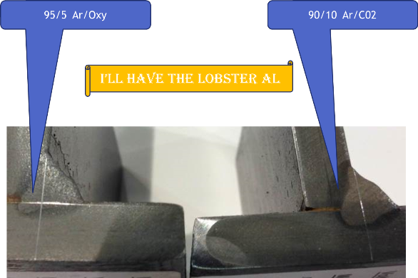
Edit:  The image may be getting beaten to death (sorry Al)  but it expresses clearly why I prefer the fusion profiles of Ar/Co2 GMAW spray gasses.

Edit, Edit:   I see different arc lengths in the images (which I am attributing to the different amounts of active gas and their affects on the transition line)  But I don't see from the picture a differing CTWD (contact tip to work distance)....  I can't see the contact tip at all and the listed data says CWTW is 18mm (.7 inches) which is typical.   I see Henry's questions regarding this but am unclear about them.

Edit, Edit, Edit;   I see there is an entire other page to this thread!  and CTWD is cleared up there.
Parent - By electrode (***) Date 11-05-2014 17:22
Lawrence,
thank you very much.
Quite similar to you recently, I will be back soon.
Comments to follow then.
I seem to understand we're approaching the finish line, however, reading: "Electrode, I'm still very curious to the point/thesis you have been ever so gracefully been steering this conversation toward.", makes me intensively thinking on what I actually wanted to say. :)
Parent - By electrode (***) Date 11-08-2014 16:39
Lawrence,
Hm... as I was already saying.
Reading "Electrode, I'm still very curious to the point/thesis you have been ever so gracefully been steering this conversation toward." after all whats's been said and done, made it really hard for me to recall on what I wanted to actually say. Ok. Actually I just wished to bridge the gap between this and another thread (https://www.aws.org/cgi-bin/mwf/topic_show.pl?pid=260853#pid260853) where we were - enjoyably - discussing on "crackling" or "sizzling" noise. Further, on how to use that as an accoustic indicator for "proper bead volume" and finally where this "crackling" was arising from. If you may remember; my opinion was that this sizzling noise comes from (very) short circuits, whereas you claimed - also referring to Mr Ed Craig - the "crackling" sound is caused by mill scale.

In conjunction to PlasmaHead2's question(s) on GMAW behaviour using one rather small wire electrode diameter I simply connected your - reasonable - quote(s) from that thread mentioned above e.g.:

- "...standard CV (Constant Voltage) machines will vary in amperage as the torch moves forward and back..." [1], as well as
- "CV GMAW the arc length remains constant." [1]
-"The crackle sound is NOT short circuiting, but rather mill scale being burned and repelled from the base metal.  As long as the open arc is visible and there is no spatter sticking to the base metal you are where you want to be." [2] and last but not least
- "Arc length is determined by arc voltage. [3]"

PlasmaHead2's question was containing the statement: "...it produced a nice hot short circuit transfer..." [4], but also: "Why doesn't anyone use .023 wire in spray arc..." [4]. So, I was wondering what actually he could have produced along with welding his ~ 1 inch long bead. Some 'short circuiting axial spray droplet transfer' or maybe an arc 'buried' underneath the workpiece surface?

The answers may be related to the shielding gas applied and since I could read another statement from yourself (along this thread here again) saying:

"I'm going to stick with my guns on the "crackling" arc.  It's simply shorter, via less arc voltage.". [5]

I thus dared - a little provoking indeed, but for sure without intending any offence - embedding images from some experiments reflecting constant boundary conditions except the shielding gas - which was altered. And, although the arc voltage was kept constant (within the experimental error) we could nonetheless notice the "arc length" varying; apparently only as a function of the shielding gas used.

In continuation to reading your statement:

"Reduce voltage until crackle is heard, but an open arc with the pinch effect is still clearly visible, and the weld is still spatter free (this is easy to do with oxygen mixes)." [6]

... I was reminded of the graphs plotted (and having been buried in my archives) using an oscilloscope along the experiments of which the arc images (contained in a previous post) have been taken from.

And, see also the embedded graph, even though we are - at least in my opinion - producing some axial spray droplet transfer while deploying one Ar + 4 O2 blend, we can nonetheless detect (brief) short circuits along the weld sequence. I have marked some of these short circuits using the arrows but from the voltage rippling - I hope - one can conceive that there's something highly dynamical going on along with the droplet transfer. All this, amongst others, brings me to hold to my previous assumption; i.e. the "crackling" ('slight' indeed but nonetheless) might arise from short circuits (relatively) brief in time.

So, now to return to your initial comment "I'm still very curious to the point/thesis you have been ever so gracefully been steering this conversation toward.".

Actually I just tried to show - particularly to PlasmaHead2 - that - sometimes - things happen not really fully fitting in to well-known theories*.

On the contary actually. Although Ar + oxygen shielding gases allow for 'small' droplets to transfer one must not forget that these 'small' droplets can be inflated remarkably (see the embedded image), finally to explode and remaining as small spatter beside the weld bead. This phenomenon - occurring when deploying especially oxygen containing shielding gases with higher performance - is well-known, thus, classified as "Explosive" droplet transfer.

I hope that all I said can make some sense - a little at least.

Regards.

* But I'm sure that we all, hooked to welding, did already know that before.

References:
[1] https://www.aws.org/cgi-bin/mwf/topic_show.pl?pid=262683#pid262683
[2] https://www.aws.org/cgi-bin/mwf/topic_show.pl?pid=262720#pid262720
[3] https://www.aws.org/cgi-bin/mwf/topic_show.pl?pid=262686#pid262686
[4] https://www.aws.org/cgi-bin/mwf/topic_show.pl?pid=262627#pid262627
[5] https://www.aws.org/cgi-bin/mwf/topic_show.pl?pid=262925#pid262925
[6] https://www.aws.org/cgi-bin/mwf/topic_show.pl?pid=262925#pid262925
Parent - By ssbn727 (*****) Date 11-02-2014 00:07
Again, with all due respect Electrode... How can you stand by that note below when the images in your post are clearly showing that the CTWD's on each of the images are differing in measurement?

"Note that a conventional constant voltage (CV) welding power supply was used for accomplishing the trials of which the embedded images stem from.
As I was mentioning in a previous post; experimental conditions maintained constant - except the applied shielding gas."

Does that include CTWD also? I don't think so according to the images shown in your previous post... Hence one of the reasons for why the note above isn't considering all of the relevant variables that would constitute "experimental conditions maintained constant."

Resulting welding parameters:

#1:
- Weld current (I): ~356 A (mean)  So the difference of 13 amps and 0.1 volt mean would produce that much of a difference between #1 & #2?
- Weld voltage: (U): ~32.6 V (mean)
#2:
- Weld current (I): ~369 A (mean) The difference between #2 and #3 is 28 amps and 0.1 volt mean... Is the rationale the same here when comparing #2 to #3? 
- Weld voltage: (U): ~32.7 V (mean)
#3:
- Weld current (I): ~397 A (mean)
- Weld voltage: (U): ~32.8 V (mean)"

This is what bothers me... How could such a minor difference in V/A variables from one image to another justify the obvious differing CTWD's when you mention in the note above without including the CTWD variable as part of the statement that "experimental conditions maintained constant - except the applied shielding gas." Could you please elaborate further Electrode?

Respectfully,
Henry
Parent - - By ssbn727 (*****) Date 11-02-2014 00:20
Again, with all due respect Electrode... How can you stand by that note below when the images in your post are clearly showing that the NTWD's & CTWD's on each of the images are differing in measurement? (NTWD = Nozzle to Work Distance)

"Note that a conventional constant voltage (CV) welding power supply was used for accomplishing the trials of which the embedded images stem from.
As I was mentioning in a previous post; experimental conditions maintained constant - except the applied shielding gas."

Does that include CTWD & NTWD also? I don't think so according to the images shown in your previous post... Hence one of the reasons for why the note above isn't considering all of the relevant variables that would constitute "experimental conditions maintained constant."

Resulting welding parameters:

#1:
- Weld current (I): ~356 A (mean)  So the difference of 13 amps and 0.1 volt mean would produce that much of a difference between #1 & #2?
- Weld voltage: (U): ~32.6 V (mean)
#2:
- Weld current (I): ~369 A (mean) The difference between #2 and #3 is 28 amps and 0.1 volt mean... Is the rationale the same here when comparing #2 to #3? 
- Weld voltage: (U): ~32.7 V (mean)
#3:
- Weld current (I): ~397 A (mean)
- Weld voltage: (U): ~32.8 V (mean)"

This is what bothers me... How could such a minor difference in V/A variables from one image to another justify the obvious differing NTWD's and possibly CTWD's when you mention in the note above without including the NTWD or the CTWD variable as part of the statement that "experimental conditions maintained constant - except the applied shielding gas." Could you please elaborate further Electrode?   (NTWD = Nozzle to Work Distance)

Respectfully,
Henry
Parent - - By electrode (***) Date 11-02-2014 13:11
Thank you, Henry.
I appreciate your comments and questions and of course I will be happy to elaborate further.

To answer the first.
I can reliably stand by my statement because the trials were accomplished under my control.
Hence, I was the one in charge of maintaining everything besides the shielding gas constant.
I.e. my name was put under the report for assuring this.

Then, I was seriously trying to understand what you mean when you say: "...the images in your post are clearly showing that the NTWD's & CTWD's on each of the images are differing in measurement.". I failed, hence, once again.

Despite the fact, that no "nozzle" can be seen in the images; the Contact Tube to Work Distance (CTWD) was held constant at 18 mm throughout the whole test. What can be seen from the embedded images just represents 3 different conditions arising from 3 different shielding gases. I seem to understand, or presume, from your comments that - eventually - you may imply constant current (?) because 3 different 'arc shapes' become visible. Deploying constant current and varying CTWD (as such of course along with NTWD) different arc shapes - perhaps similar to those depicted - may result. It was - however - constant voltage; CTWD was kept constant and camera position has remained unchanged throughout in order to assure constant experimental conditions for making the trials comparable among themselves - in my opinion the only way it works. Mingling with further affecting parameters - as unfortunately quite often noticeable in research- or 'purely 'theoretical' papers - was excluded. Pure experimental research - focusing on only 1 influencing parameter: the shielding gas along with adjusting "spray droplet transfer". Btw I suggest that the power supply did quite well in maintaining the voltage constant, don't you mean?

I will additionally try another approach to make it maybe clearer.
Assuming we are having a specimen finite in width + height but infinite in length and could use a device capable of switching the shielding gases as required.
We shall use a longitudinal manipulator - or weld robot even - and shall adjust all parameters as listed previously for maintaining them constant throughout the whole weld sequence.
Now we start welding with Ar+18CO2 and monitor the weld parameters until constant conditions are achieved.
Then we are switching the shielding gas from Ar+18CO2 to Ar+10CO2. Presuming a gas hose of ø 10mm and hose package length (incl. the hose from the bottle to the power supply) of 4.5 m, obtaining a total hose length of ~ 6.5 m, and adjusting 15 l/min gas flow rate, it would take us roughly 2s to have the new composition at the weld pool. To assure that we are really applying Ar+10CO2 we add appropriate time and use the changed output variable (current) as an additional indicator. Then the same play with Ar+4O2. Nothing has changed - except the shielding gas.
This is quite a similar scenario to what's depicted by these 3 little images.

I hope that can make some sense.

Regarding NTWD, of which I presume the gas nozzle is being meant by yourself here.
Welding's been performed using an experimental set up as already previously indicated.
That is. Within the systematic experimental error, NTWD was constant as well.

So. What's the mystery behind all that?
As I did mention already. If, as already discussed, arc length can be considered proportional to arc voltage, may the arcs depicted then maybe have had the same "length".
If so, was it then, that the Ar+18CO2 arc was eventually yet buried (in part at least) below the surface?
And if so. Was it then, that the Ar+18CO2 spray arc had a proportionally higher fusion depth vs. the Ar+4O2 spray arc?
Questions within questions.
Parent - By ssbn727 (*****) Date 11-02-2014 20:52 Edited 11-04-2014 06:54
I can understand the logic in your explanation... However, for my curiosity what was the CTWD or NTWD on this experiment?
As far as the arc being buried that's something to observe from a different angle as far as where I'm observing so I cannot debate that except to say that from where I'm looking at none of the images are showing a buried arc... Each one of those images clearly shows a very visible arc IMHO... Now I do notice that there's more penetration in some of the images when comparing each of them to one another but the plane that represent the surface of the work - meaning the metal is clearly distinguishable... What I notice are the differing metal transfer sub-modes for what can be loosely labelled as spray arc transfer...

This entire exercise is a very good example of what happens when  critically important details are either purposely, or neglectfully omitted... The results are clearly questionable at best... I suggest that you use clearer images because if it were myself I know I would use the clearly visible detail oriented with 3D reference points or dimensions within the images to describe pertinent differences in the varying gas mixes used for shielding because no disrespect, but they are not ideal at all for what you want to express and clearly describe and I'm talking about looking at this from an educational perspective - meaning and being very blunt when I say this - a lousy choice as a visual aid to use in a teaching environment or for a demonstration...

The NTWD & CTWD are an estimate I'm making based on the ever so slight and hardly visible clues I was able to discern and yet as it is with just about all estimations derived from awkward to say the least examples shown in the images in question - meaning I could be wrong about those barely visible features since they're just an estimate...

You can stand on your claims. and I cannot honestly contest them without any more clearer evidence that what is available in those images but the demonstration of your findings are how shall I say this with diplomacy? Not the optimal choices to use for visual examples to demonstrate your findings.

Edit: May I suggest that the next time you use an image similar to the images you previously posted, a slight amount of background lighting... Just enough so that one can make out the CTWD & NTWD clearer and without any ambiguity as i experienced with your images... now as far as answering my question as to whether or not my eyes were plaaying tricks with my mind... The obvious answer is a resounding yes! Are you related to Sherlock Holmes or Doctor Watson?:grin:

Respectfully,
Henry
Parent - - By ssbn727 (*****) Date 11-04-2014 09:17
Hello again Electrode,

This thread has me thinking of the purpose of your experiment... I then reviewed those 2 questions you left at the end of your last post reply to me... And from what I could come up with thus far is this...

1.) If so, was it then, that the Ar+18CO2 arc was eventually yet buried (in part at least) below the surface? Yes... In fact I did notice the deeper penetration...

2.) And if so. Was it then, that the Ar+18CO2 spray arc had a proportionally higher fusion depth vs. the Ar+4O2 spray arc? When you wrote "Higher fusion depth" I believe what you really meant to write was: "Deeper fusion depth" instead, correct? Again Yes...

I did something ot alter the images by inverting the color of each one and much to my surprise, I came to the conclusion that your absolutely correct in your previous statements and I only regret that I should have thought of doing this old image trick I learned so long ago... Because it definitely revealed that in each of the images and based on the reference measurement of 1mm, the inverted images clearly show that there isn't any sort of Contact tip or shadow of one, and the same goes for the nozzle also... So please accept my apologies for over-pursuing and questioning of your images and results... I'm going to attach the inverted images so you can see for yourself what they revealed to me.:eek::roll::smile::grin::cool:

I can see clearly now - the rain is gone! I can see all obstacles in the way! Well, you know the rest...:grin: man o man has this been a revealing thread as well as a long one at that.:lol:

Respectfully,
Henry
Parent - By electrode (***) Date 11-05-2014 17:26
Henry,
Nice work. Thank you.
As I was responding to Lawrence a few minutes ago.
I'll be back at the soonest and yes, your post confirms what I was presuming.
Apparently - to me at least - we're approaching the finish line.
Parent - - By ssbn727 (*****) Date 11-01-2014 02:14 Edited 11-01-2014 10:14
Hmmm,

Either my eyes are failing me miserably or am I seeing in the images three different looking CTWD's Electrode? And I ask you this because the reference measurement of 1mm in the image shows that the size of the arc plasma streams vary in size There is also from what I see a variation in the height distances from the weld pool to the location within the plasma stream on the electrode "cylinder" where the "lorentz" and other forces also start creating a pinch effect @ the electrode cylinder... So please tell me that my eyes aren't playing tricks with my powers of observation...:surprised::roll::grin:

This study report was written & submitted to the Office of Naval Research back in September of 1989 by Donald M. McEligot of
The Hydro-thermodynamics Research and Technology, Westinghouse Electric Corporation - Naval Systems Division. The title of this report is simply: "Metal Transfer in Gas Metal Arc Welding." This is an older study report and much of the visual example are drawing as opposed to videos but, I think you'll find the study interesting in knowing how they thought regarding the various theories of the  phenomena involved in Metal Transfer in Gas metal Arc Welding back then... Here's the link to the report:   
http://www.dtic.mil/dtic/tr/fulltext/u2/a213390.pdf

Here's an interesting article published in the monthly AWS Welding Journal in June of 1993 titled:
"Analysis of Metal Transfer in Gas Metal Arc Welding" written by: Y-S.Kim and T. W. Eagar. "This study shows that the transition of metal transfer mode in gas metal arc welding occurs much more gradually than is generally believed" Here's the link to the paper:    http://www.aws.org/wj/supplement/WJ_1993_06_s269.pdf

Here's another very interesting paper titled: "Dynamic analysis of globular metal transfer in gas metal arc welding—a comparison of numerical and experimental results" Received by J. Phys. D: Appl. Phys. 31 (1998) 2929–2941. Printed in the UK on June 19th, 1998 and written by H. G. Fan and R. Kovacevic of the Department of Mechanical Engineering, Southern Methodist University. Here's the link to a much more thorough and informative paper which I know you'll appreciate:

https://www.smu.edu/~/media/Site/Lyle/RCAM/Publications/3%20Dynamic%20Analysis%20of%20Globular%20Metal%20Transfer%20in%20Gas%20Metal.ashx?la=en

This paper is titled: "Heat and mass transfer in gas metal arc welding. Part II: The metal J. Hu 1 , H.L. Tsai * Department of Mechanical and Aerospace Engineering, University of Missouri–Rolla. Received 18 January 2006; received in revised form 22 August 2006 Available online 24 October 2006... Here's the link to this paper which I know you'll appreciate even more so:    http://web.mst.edu/~tsai/publications/Hu-IJHMT-2007-2-61.pdf

This thesis draft is from Erik J. Soderstrom as part of the requirements for the degree of Doctor of Philosophy (Metallurgical and Materials Engineering from The Colorado School of Mines on March 25th, 2009.

"ABSTRACT: The objective of this research is to study the thermal balance in the electrode during different metal transfer modes in Gas Metal Arc Welding (GMAW). On a scientific and engineering level, metal transfer contains many fundamental mechanisms that are not completely understood. The approach is both analytical and experimental.
One aspect of this research is the design and implementation of a testing platform that has the ability to simultaneously characterize different aspects of the GMA welding process. Metal transfer modes are analyzed with a high-speed laser imaging system that is synchronized to the current and voltage signal. Energy measurements of both the detached droplets and weld ing arc are made on two separate calorimeter systems. Process efficiency, droplet heat content, and droplet temperature measurements are conducted for a variety of transfer modes using ER70S-6 steel, ER316L stainless steel, and ER4043 aluminum electrodes. Trends show a relationship between droplet heat content and metal transfer modes.

The setup also enables a novel procedure to estimate electrode fume formation rates based on a combination of chemical composition analysis and a mass balance. A second aspect of this project is to develop a theoretical model that characterizes the heat transfer mechanisms in the electrode. The distinctive characteristics of the modeling effort are the incorporation of heat lost by evaporation from the electrode tip, the influence of fluid flow within the molten droplet, and the distribution of electron condensation energy on the anode.

Evaporative heat losses may dominate heat transfer with aluminum-based alloys, but appear to have lesser influence in ferrous-based alloys. Heat transfer within globular molten droplets is dominated by convection, regardless of material. A shift to conduction begins at the transition, as electron condensation energy engulfs the droplet and is deposited on the solid electrode. In higher current spray transfer mode, conduction dominates because of the small liquid layers present in the system. By combining both of these approaches, a semi-empirical heat-transfer model is developed for the region between the contact tip and the plasma. Arc/electrode interactions not only influence the metal transfer mode but also the heat transfer occurring in the liquid droplet and adjacent consumable material." Here's the link to the Thesis:

http://digitool.library.colostate.edu///exlibris/dtl/d3_1/apache_media/L2V4bGlicmlzL2R0bC9kM18xL2FwYWNoZV9tZWRpYS8yMTI3MDA=.pdf

This one I know you will find interesting and enjoy as well as appreciate that it's origin is from Cranfield University's CRES School of Applied Sciences and written as a PhD thesis written and submitted by Nuno da Costa Pepe for the academic year of 2009 - 2010 and titled: "Advances in Gas Metal Arc Welding and Application to Corrosion Resistant Alloy Pipes." Here's the link to Cranfield University's CERES @ SAS that will enable you to download the .pdf:

https://dspace.lib.cranfield.ac.uk/handle/1826/4501?mode=full&submit_simple=Show+full+item+record

As a bonus, I'm including a short movie I know you'll appreciate that is found in the Department of Materials Science and Metallurgy of the University of Cambridge in the UK. The movie presented here has kindly been provided for teaching purposes by Professor T. DebRoy of the Department of Materials Science and Engineering, Pennsylvania State University U.S.A.. Oh and you can use it as a desktop wallpaper or a screensaver too... Here's the link to this .avi movie:

http://www.msm.cam.ac.uk/phase-trans/2001/debroy.html

This paper is from HAL archives - ouvertes of France titled: "Experimental analysis of droplet-gas interaction during GMAW process" Written by Julien Chapuis, Edward Romero, Fabien Soulie, Cyril Bordreuil.... Here's the link:    https://hal.inria.fr/file/index/docid/808052/filename/Experimental_analysis_droplet-gas_Chapuis_al.pdf

This paper is from the University of Kentucky which was my Grandfather's Alma mater titled:"Numerical Analysis of Metal Transfer in Gas Metal Arc Welding" Written by G. WANG, P.G. HUANG, and Y.M. ZHANG. Here's the link:    http://www.engr.uky.edu/~ymzhang/Papers/George%20Paper%20One.pdf

This paper is more mathematics and Physics influenced and is another "oldie but goodie" titled: "Analysis of Arc Pressure Effect on Metal Transfer in Gas-Metal Arc Welding by Sehun Rhee and Elijah Kannatey Asibu,Jr. Department of Mechanical Engineering and Applied Mechanics, The University of Michigan. Here's the link below:

http://deepblue.lib.umich.edu/bitstream/handle/2027.42/70584/JAPIAU-70-9-5068-1.pdf?sequence=2

This last one is from two institutions of higher learning titled: "Effect of welding current on metal transfer in GMAW" Written by M.St. Wêglowski (a), Y. Huang (b), Y.M. Zhang (b)
(a) = Institute of Welding, ul. B³. Czes³awa 16/18, 44-100 Gliwice, Poland, (b) = University of Kentucky, Lexington, KY 40506, USA. Here's the link:

http://www.archivesmse.org/vol33_1/3318.pdf

I have many, many more but I'm watching a rerun of The Shark Tank on "On Demand" TV so I'm going to end it here... Enjoy the papers!:grin::lol::cool:

Respectfully,
Henry
Parent - By PlasmaHead2 (***) Date 11-01-2014 16:52
Thank you Henry!
I'm downloading that little video of the weld pool...
Up Topic Welding Industry / Technical Discussions / Spray arc .023 wire and why is it "wrong" ?
1 2 3 Previous Next  

Powered by mwForum 2.29.2 © 1999-2013 Markus Wichitill