Not logged inAmerican Welding Society Forum
Forum AWS Website Help Search Login
Up Topic Welding Industry / Technical Discussions / Contact Tip to Work Distance "CTWD"
1 2 Previous Next  
- - Date 02-08-2015 22:16
[topic branch moved]
Parent - - By 803056 (*****) Date 01-29-2015 13:42
Whenever a client is having problems welding carbon and high strength low alloy steels with GMAW, I revert to SG-AO-2% as the "standard." The mix will provide a stabile base for spray mode transfer. Once the machine is "zeroed in" and the welders are accustom to the operation I switch to the gas of their choice and let them determine which shielding gas provides the most stabile operating characteristics. 

The oxygen in the shielding gas affects the surface tension of the weld pool and flattens the weld bead. They quickly see that "pushing" the gun usually results in excessive undercut while "pulling" the gun reduces undercut to acceptable levels.

Some insist on using SG-AC. In that case I limit the CO2 to about 10 to 12% so that the spray mode transfer is stabile.

Personally, I have no preference for production as long as the welder is operating within the listed welding parameters and the weld is meeting the acceptance criteria.

I use the fillet break test to verify fusion to the joint root is obtained. If not, the welding parameters are tweaked to get the required fusion to the root.

Usually, if there is a problem, the welder is not working within the prescribed range for electrode extension, arc voltage, and wire feed speed. Notice I did not mention welding current. The omission was intentional. Setting the machine using welding current is a fool's game.

The use of SG-HeCO for austenitic stainless steel appears to be the current norm, especially when using the pulse spray transfer mode. It appears to work. If the client is happy with the results, I don't rock the boat.

Best regards - Al
Parent - - By wrenchtech (*) Date 01-31-2015 05:20
Al, why do you say that setting wire feed and voltage to produce a desired amperage is a fools game?

It's not something I usually do but I think i could learn something here.
Tom
Parent - - By 46.00 (****) Date 01-31-2015 06:37
Do you ever see an amperage knob on a MIG machine?
Parent - - By 46.00 (****) Date 01-31-2015 06:38
think stick out!
Parent - By Superflux (****) Date 01-31-2015 07:32
Contact Tip to Work Distance..
CTWD RULES!!!
Consistency.
Nuff said.
Parent - - By wrenchtech (*) Date 02-01-2015 06:31
Well, none of you answered my question really. 
And of course there is no amperage adjustment on a CV machine.  I do have a couple of welders with an amperage readout.
In a fully automatic situation - like a bore welder for example, the stickout never changes but you can change the amperage with wire speed and/or voltage.  I don't know why you you'd want to do things that way but I've seen it done.  I watched a fella operating a bore welder fiddle that way until he got the amperage he wanted. 
I don't know why he did things that way.
So I didn't think it was such a stupid question.
Parent - - By aevald (*****) Date 02-01-2015 07:48
Hello wrenchtech, from my perspective a simple question such as the voltage/amperage relationship in CV mode is definitely one that can have a lot of variables and results attached to it and not so simple to address.

You may have seen comments from people where they have a particular Lincoln wire machine(one of the all-in-ones) and they say that they like the arc characteristics of it much better than a similar Miller machine or the same statement comparing an ESAB machine of this type to another manufacturer. These particular example machines rely on a pre-determined ratio of voltage to amperage with the variable for altering this range of ratio by increasing or decreasing wire speed. Make these comparisons with different diameters of wires and things may take on a different look as well, cross-sectional wire density is an additional component of the welding recipe that alters the end results of the weld bead.

When things such as variable inductance adjustments can be included, inductance tap selection may be allowed for, or other conditions such as elevated phase switching speeds of incoming AC power and changes in the type/method of DC rectification are thrown into the mix things can become complicated quickly. All of these variables can effect arc characteristics and capabilities and the appeal for a specific combination that yields visually desirable and metallurgically sound weld bead results.

Look at this from another angle: voltage and amperage "ranges" are specified and generally qualified for specific applications in welding. When you have the WPS that you are expected to weld to you could theoretically select a voltage within the specified range and vary the wire speed to stay within the specified amperage range or you could work the other way and select a wire speed and vary the voltage so long as you stay within the limits specified in that WPS. Which ever way this plays out, the resulting weld deposit will be different and likely allows for the operator to weld as he/she likes to. Testing and documentation of this process should be complete enough that no matter which end of the range you are on or if you are anywhere in between the resulting weld deposit should meet it's intended target for performance in it's specified application. An interesting topic and good to know more about. I always look for ways to learn more and most likely this response will illicit responses to help me with that goal. Best regards, Allan
Parent - By wrenchtech (*) Date 02-02-2015 14:20
Ah, now this makes sense.
Thanks for the reply.
I know nothing about variable inductance adjustments or or phase switching speeds of incoming AC but neither sound like there is anything I could do with them anyhow.
But in the example i gave above I can see why he would adjust the welder to get an amperage that would would leave the most efficient sized deposit.
Hmmm.  I don't do it that way but maybe I should try it out. 
Thanks!
Parent - - By electrode (***) Date 02-02-2015 15:36
Allan,
I do like your settled, unagitated way of explaining tricky things very much - really.
I was wondering though whether you did comprehend the 'wire feed speed vs amperage' plot, depicted in another post.
Surely overlooking something simple here, but with all due respect I'll have to confess: It remains impenetrable to me.
Thank you.
Parent - By Lawrence (*****) Date 02-02-2015 16:10
A WPS communicates to two different audiences:

1.   Welders

2.  Auditors

Welders don't care about amperage.

Auditors don't care about Wire feed speed.

A well prepared WPS provides the *Welder* with a crafted wire feed speed range for GMAW that has (by trials) made a controlled deposit possible at the top and bottom of the WFS range that includes consideration to the top and bottom of the CTWD or stick-out range.

A well prepared WPS provides the *auditor* with a compliant current range, ether prequalified or in accordance with a PQR. 

If the welder obeys the WFS and CTWD on the written WPS. The current will be within the range presented on the WPS as well.

I do like the digital feedback functions of some of the newer GMAW equipment..  Where the average weld current for the weld blinks on the feeder readout for 5 seconds after each weld is completed... This gives the operator some quick narrative on things like stick-out and gun angle, or machine calibration.  But the welder is almost always going to depend on WFS settings to do his/her work.

We have some GMAW power supplies that have the WPS ranges for WFS and voltage *locked-in*,  We can see every weld that is made outside of parameters and generally know why....  current high?   current low?  voltage low?  can all be attributed to stick-out, gun angles or wire feeders slippage and quickly corrected before many bad welds are made.

If the process is under control... The supervisors should *KNOW* what current is expected for a given WFS and wire diameter and CTWD.
Parent - - By aevald (*****) Date 02-02-2015 17:22
Hello electrode, I have to admit that when I view/read through many of the posts that cover a particular topic that I often "miss" things. At times this happens when there isn't enough information presented and I make "assumptions" or when I misread or misinterpret information as well. There may even be times when I make a statement expecting to be corrected and informed in a much better way and to form a better understanding.

Your question has me wondering a bit also. Are you asking if I know the relationship between wire speed and how it affects amperage? I believe that I do, yet maybe I am missing something. Please don't hesitate to "spell it out" for me. Best regards, Allan
Parent - - By Milton Gravitt (***) Date 02-02-2015 18:25
Allan it is called being human.

     M.G.
Parent - By aevald (*****) Date 02-02-2015 19:52
Yes Milton, you are certainly right about that! Thanks for the reply. Best regards, Allan
Parent - - By electrode (***) Date 02-02-2015 18:59
Thank you for both responding and asking, Allan.
I suspect that we are ending up similarly as when it comes to reading (through) some threads.
One must keep his eyes open and his senses sharpened to not get lost at a particular stage - sometimes at least.

Of course I don't have any single doubt that you're more than thoroughly understanding the relationship between wire feed speed and current.
Besides the whole discussion, to me personally, because there's proportionality between both, it actually wouldn't matter which value is being chosen for producing a specific weld deposit.
Of course also, I'm not sure whether every CV GMAW machine has the ability to display the current.
That is. If the welder has no amperage displayed to look at, of course the current has not disappeared but is yet there as a function of wire feed speed.
Lawrence's answer was most valuable as well in this respect (thanks for that btw) because of splitting the whole issue into the 2 different (practical) approaches to be addressed.
The Auditor - as I presume - is rather uninterested in wire feed speed since - theoretically - not being part of the "game" (mainly) controlled by voltage and current, whose - sometimes - complicated interplay finally affects interior and exterior weld quality. The welder again - Mea Culpa(!) and may the exception prove the rule - may not really have an interest in which electrical parameter is individually and quantitatively affecting the weld in which way.

Regarding your question.
Definitely no ulterior motive here with me.
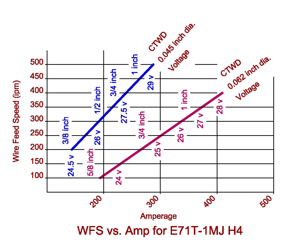
I was just wondering how to read the graph plotted by Al Moore - and, not to forget, much appreciated by myself.
According to what's been explained and described along this thread - given a constant voltage machine is used - the current must decrease as the electrode extension rises.
The drawing makes sense to me as the voltage rises with the current, the latter being a function of the wire feed speed.
I'm just struggling which part the contact tube to work distance (CTWD) plays here.
Does the slope represent a rising current with increasing CTWD?
I have no idea how to connect that.
That being said, was the reason for friendly asking whether you may have understood it better than me.
But, like I already said, most likely I'm simply overlooking something here.
Thank you again, anyway.
Parent - By aevald (*****) Date 02-02-2015 19:35
Thanks for the reply Electrode, you brought home an issue that I generally don't address with proper reasoning and information when having discussions with students.

Myself, I believe that in that area(electrode extension) I have been fortunate over my career to have not experienced that as an issue with the welding that I have performed(I'm not bragging about my skills by any means nor even trying to say that I had the knowledge to know the difference, just never had the issue brought up nor had it explained in any detail).

This thread has brought to light more than a few pieces of information that can be beneficial to just about everyone. Often we simply weld and as long as everything is working as we "believe" that it should be we are not interested in all of the theory of how everything works or even why. There are basic items: such as CV current and it's application to GMAW/FCAW/MCAW, wire speed(tied to amperage in relation to voltage present in GMAW/FCAW/MCAW process, and amperage relative to CTWD as has been brought to light in various parts of this thread. I'm a little less foggy in the head I believe, but questions certainly still remain.

To add to your mention of slope, I have always had issues with understanding slope and also inductance in most instances. This is likely because I have difficulty, in my "simple" approach, to understand the complex portions of these components of welding and how they interact with the other characteristics and variables that make up an electrical welding circuit/path. To further address your final question, I'm afraid that I have not taken the time to look closely enough to respond. Yet, I can probably say that I will need assistance as well. Thank you and best regards, Allan
Parent - - By aevald (*****) Date 02-02-2015 19:47
Hello again Electrode, I just had a closer look at the graph that Al included and this is how I believe that it is designed to be read: in one instance you are looking at a blue line representative of .045 solid wire and it starts at 200 ipm of wire, set to 24.5 volts, and delivering roughly a 100 amps, with a CTWD of 3/8". As the extension is increased without changing any other variables, the amperage increases as well as the voltage, so disregard the left column that list the wire speed. For any of the other examples, consider only the starting wire speed, voltage callout and the starting amperage. As you view the increase in amperage do not look for a correlation to the wire speed it is the same as when starting and as CTWD increases only look to the amperage and voltage portion of the graph to note the increases. Now here again I could be reading this completely wrong and if so I will certainly expect a correction. Best regards, Allan
Parent - - By electrode (***) Date 02-02-2015 21:05
Thank you again for your both responses, Allan.

Following your explanation I suspect to have it read as you do.
And exactly this is what I cannot fully comprehend.
Following the slope (blue line as been treated in your response) it starts at 24.5 V.
Given that a CV machine is used and all variables are maintained constant except the electrode extension (quote: "As the extension is increased without changing any other variables...") then here comes where I begin to struggle.
If we are not changing the voltage (CV characteristic) and not changing the wire feed speed, then I suggest both voltage and current constant.
If we are now changing the electrode extension (given wire feed speed and voltage constant) from 3/8" to 1", then, in my understanding, the voltage remains constant (CV characteristic) and the current must decrease due to increasing the resistance over the greater CTWD. However, involving both axes (this is what a diagram actually is made for) then I could draw a line from both axes to intersect the blue line; representing a slope that shows CTWD, voltage, and amperage increasing although the resistance should actually drop the current at constant voltage.

So, in my interpretation the graph plotted involves actually 4 axes. Amperage (primary x-axis); Wire Feed Speed (primary y-axis); Voltage (which might be put at a secondary y-axis) and CTWD (maybe to put on a secondary x-axis). Not sure how that would interact with the values plotted, but including the slope(s) and relating it to 2 different values (voltage and CTWD) does - slightly - confuse me.

You see my point? Am I overlooking something fundamental?
Easily conceivable, of course. Human actually, as been put by Milton Gravitt.
As I say; I do remain struggling here.
Parent - - By aevald (*****) Date 02-02-2015 22:01
As one of the sayings goes Electrode, I guess I am just going to have to venture out into the shop and put this theory to the test. I have little doubt that Al has led us astray and I'm sure that I will have a "learning" moment. Best regards, Allan
Parent - By electrode (***) Date 02-03-2015 06:47
Thank you, Sir.
Maybe the graph would make somewhat more sense when reversing the CTWD values; i.e. correlating the highest current to the lowest CTWD and vice versa. Anyway, I fully agree with you. Little doubt that Mr Al Moore would have led us astray. The theory should stand the practice hence - sure that will answer the open questions and if so, most likely will be revealing new ones. Absolutely no doubt however; you will provide us all with this magic "learning moment".
Thank you again and kind regards.
Parent - - By electrode (***) Date 02-07-2015 16:53
Allan,
just out of curiosity.
Did you already find time to "put this theory to the test" as was your intention; checking thereby its correctness?
Btw I made use of the 'Melting Rate + Penetration' video link, posted by Lawrence.
Relating it to some specific melting rate this video at 3:14 ≤ t ≤ 3:50 depicts electric current and contact tube to work distance ("stickout") data.
I've used these in order to figure out whether the graphs producible may follow some similar slope, see embedded chart.
It is as we have discussed. As CTWD increases (and supplying constant voltage); current decreases.
Hence, differently to what is drawn in the questionable diagram it shows what we have already discussed.
I'm afraid to stand my ground - the diagram is misleading.
Surprisingly (or maybe not?) everybody else obviously does condone that.
What am I missing here; or could you prove it working through your test(s)?
I'm really curious and any feedback is gratefully acknowledged.

Kind regards.
Parent - - By aevald (*****) Date 02-07-2015 17:48
Hello electrode, I did in part. I can't determine how exactly Al's graph "works" I know that the information is likely there, but no, I can't figure out how to apply it as I am seeing it/interpreting it. I just need to have Al explain it in a manner that my thick head can cipher it.

One quick test that I did utilized an FCAW CV power source(Miller XMT304 CC/CV) set to approximately 25.5 Volts and roughly 330 IPM of wire speed utilizing .045 Corex Versatile E71T-1 wire, shielding was 75Ar/25Co2. With approximately 3/8" CTWD amperage was a little over 200 amps, with approximately 1" CTWD the amperage dropped to around 150-160 ish. The voltage stayed fairly constant, at least according to the digital meters on the XMT. All of the information regarding Voltage and Amperage was determined from the digital meters on the XMT. The wire speed was determined by running the wire for 6 seconds, measuring it's length and multiplying by 10. Not completely scientific, but certainly good enough to see contrasts.

I am hoping to be able to do some video of the meters while welding is taking place to show and explain in more detail the relationship between CTWD and delivered amperages. I have hopes to video each of the various CTWD lengths and the resulting meter readings.

I have had instances where students have had a vertical bead "fall out", in other words they have been vertical welding with an upward progression and as they are progressing along the weld joint the wire has dug into the part and the weld puddle has fallen out and run down the face of the bead.

My explanation typically has gone along these lines: if you are running on the higher side of wire feed speed you "can" experience a physical pushing into the weld pool by the wire and if you are not relatively consistent with your travel speed and stick-out distance there will be a negative effect on the bead profile and size. Another explanation that I mention has to do with the surface condition of the welded parts, if they have heavy rust or scale it generally requires more energy to melt this surface material than the "clean/pure" metal underneath the surface. Hence the contributing factor to preventing forward travel and having the weld puddle lose it slag-induced damming effect and loss of surface tension to draw it along and hold it in place in order to solidify correctly.

With the information concerning CTWD I believe that a large part of my description for vertical bead issues causes is directly attributable to the CTWD component of wire welding.

As to bead profile, penetration, and control and how CTWD applies, I will likely have to take a harder look at ways to incorporate more information to both explain and assist with understanding how to better incorporate the correct information. Thanks for the reminder electrode, I look forward to more information in these areas. Best regards, Allan
Parent - - By electrode (***) Date 02-07-2015 18:11
Allan,
then your test did actually prove what we had discussed or presumed respectively, and what the video-image connected to Lawrence's link was revealing. I really appreciate your detailed response. Not sure about the average metallic sheath thickness of one ø 0.045" tubular wire electrode. But in addition it would be interesting to compare the metallic cross sections of one ø 0.045" tubular and one solid wire having the same diameter.

Thank you again and kind regards.
Parent - - By aevald (*****) Date 02-07-2015 18:46
Hello again electrode, with regard to "cross sectional density", from what I have been able to learn or reason through about metallic-ally sheathed wires containing flux, solid wires, and metallic-ally sheathed metal cored wires, there is some level of efficiency that is influenced by the particular choice. A certain amount of energy is expended when welding wire is converted to a weld deposit.

So when folks talk about deposition rates relative to process and application, different wire types will shine in some places and fall short in others. Some of the best examples of this sort of thing to me would be to consider the SMAW process: if you have an 1/8" E7018 electrode and compare it to an 1/8" E7024 electrode with welding performed in the flat position the choice would be relatively simple, higher deposition rates are built-into the E7024, however, if the deposit requires a low-hydrogen consideration then it may be a moot point and the E7024 might not be allowed. I would venture to say that when you make similar comparisons with the various types of wires of like diameters that you can apply some of the same reasoning.

Accordingly, clean-up is a point of consideration, welding position will play into the choice, material type(no flux-cored aluminum wire or metal-cored aluminum wire), equipment type(not a real need for pulse and advanced process arc control with flux-cored wire process, don't know about metal-core)and I am sure many others that aren't coming to me right now.

Definitely good exercise for the brain, yet I have probably hijacked this thread to death, should probably start another thread for further discussion on these topics. Thank you for your input and participation, electrode. Best regards, Allan
Parent - - By electrode (***) Date 02-08-2015 11:20
Thank you again, Allan.
I consider your explanation for respectively E7018 and E7024 electrodes most valuable.

What I was however rather thinking about, was how much choosing a tubular wire may affect the phenomenon that you described with one of your students/applications. It is known that the heat flux into the wire (electrode extension) can be described applying a heat conduction expression. Without going too much into detail here, it is known that these equations involve temperature dependent parameters. Some of which are more (e.g. thermal conductivity, electrical resistivity), some of which are less (e.g. specfic heat) affected through temperature. My thought is. Unaware of the exact data on the metallic sheath thickness of the wire you've used; I heavily presume that your student would obtain a different weld (bead) behaviour when replacing the tubular by a solid wire electrode of similar outer diameter (OD). Simply because of the electrical resitivity should differ between a solid and a tubular wire. Then, given that the metallic cross section of a 0.045" OD tubular wire is less vs. one solid wire; the current density j = 4I/(pi*d²) should rise vs. a solid wire of similar chemical composition. Not really sure, but I seem to recall that this is one of the reasonable arguments sometimes chosen by the tubular wire manufacturers; i.e. higher current density (due to lower metallic cross section) leads to more predictable penetration behaviour or "safer" penetration in general.

Anyway, apart from that, this should also affect the amount of Joule's heating along the wire extension. Electrical resistivity might be considered inversely proportional to electrical conductivity; the latter dropping with increasing temperature. To come full circle. I suggest that the effect of "steering" the current (or "heat input") through varying wire extension is less distinct when deploying tubular wires. This might lead to additional thermal input to the weld pool. Provided specific conditions (e.g. vertical up welding with "running on the higher side of wire feed speed") that again may result in issues similar to those with your student's application. And, as easily conceivable, there is a sensitive relationship between the wire feed rate and thermal conditions along the wire extension, in my opinion not even been touched herein. By all means. This whole subject, as ever when "digging below the surface", is, in my opinion, one of the most interesting and not yet entirely understood problems in welding science.

Thank you again and kind regards.
Parent - - By aevald (*****) Date 02-08-2015 17:10
Thank you electrode, you've presented some information that is definitely above my pay grade, although, I believe that I somewhat grasp all of what you are saying. At the same time, my example of some conditions that were present or occurred with FCAW-G in an upward vertical progression I don't believe could be replicated by using solid wire, at least not with the technologies that we have in our shop. I will definitely read over the information that you have presented(probably a dozen times or so) to see if I am not seeing it for what you intended. Thank you again and best regards, Allan
Parent - - By electrode (***) Date 02-08-2015 17:57
You're a gentleman.
Thank you for your friendly response and my sincere apologies for writing long-winded.
Certainly it was not my intention.
Kind regards!
Parent - By aevald (*****) Date 02-08-2015 22:16
Not long winded at all electrode, I enjoy a challenge when it comes to information and learning. That's what keeps life interesting, Right? Best regards, Allan
Parent - - By Lawrence (*****) Date 02-02-2015 20:02
Slope and inductance:

Here is a thread where it is discussed fairly well.

I explain what is actually happening with Inductance

Al expertly explains why.

http://www.aws.org/cgi-bin/mwf/topic_show.pl?pid=77719;hl=inductance

.
Parent - - By aevald (*****) Date 02-02-2015 20:13
Thank you Lawrence, it is highly likely that I have indeed seen this post and read it and at the time didn't pay enough attention to it's contents nor it's importance. An immense "thank you" for linking it in here. Best regards, Allan
Parent - - By ssbn727 (*****) Date 02-03-2015 10:42
Hi Allan,

I apologize for posting a bit late on this topic of slope, inductance and Lawrence did provide a good link to Al's descriptions of the differences between Slope and inductance and how they relate to welding power sources of both Constant Current and Constant Voltage or Potential (CP) power source electrical output characteristics... On a side note: I am especially fond of inductance because of the name of the units of measurement for inductance being in "Henry's":grin::cool:

I just wanted to add a few links for anyone else who wants explore these topics as described by various reputable sources and I'll start with the first one from ESAB:

http://www.esabna.com/euweb/mig_handbook/592mig3_1.htm         The Power Source

http://www.esabna.com/euweb/mig_handbook/592mig3_2.htm          Voltage

http://www.esabna.com/euweb/mig_handbook/592mig3_3.htm          Slope - part one of two

http://www.esabna.com/euweb/mig_handbook/592mig3_4.htm          Slope - part two of two      

http://www.esabna.com/euweb/mig_handbook/592mig3_5.htm          Table 3-1

http://www.esabna.com/euweb/mig_handbook/592mig3_6.htm          Inductance - part one of two

http://www.esabna.com/euweb/mig_handbook/592mig3_7.htm          Inductance - part two of two

This is from the Lincoln Electric's MIG/MAG Welding Guide -Go to pages 8 through 11 in the book which would be pages 13 through 16 of this .pdf

http://www.locost7.info/files/tools/Lincoln+MIG+Welding+Guide.pdf

This is a pretty basic description of Slope and Inductance and how they relate to Short Circuit transfer in GMAW, or SCT published by The Fabricator:

http://www.thefabricator.com/article/arcwelding/choose-wisely-when-welding-thin-sheet

P.S. As a bonus, if you look for table 1 in the article and click on the label, you will be linked to a reference chart that provides parameters for welding thin carbon steel and stainless steel...

I like this description also and is published by The Welding Advisors:

[b"]Slope Control

With reference to the standard graph expressing the relationship between current and voltage.

Constant Voltage power supplies would present a horizontal line or one of a limited slope down. This would be adequate for high current density and for Spray Arc.

When using small size wires and low currents, however, that is for Short Circuit Transfer Mode, there is a need to limit the amount of short-circuit current that the power supply can deliver.

A high short-circuit current generates a powerful "pinch-effect" or magnetic squeezing force that separates violently the molten drop from the wire.

If the short-circuit current is limited to a moderate value, by selecting a suitable slope, the detachment will be smooth with no or little spatter.

Note that if the slope is too steep, the current will be too low, and the unmelted electrode will stick to the work.


Variable Inductance

Inductance control regulates the time rate of current change in response to changes in the circuit.

Adding some more inductance may prove beneficial in developing a more stable arc initiation.

One of the Mig-welding-tips that can have practical influence is the following.

In Short Circuit Transfer Mode inductance limits the pinch effect, which will be applied more gradually, by controlling the rate of current rise in time.

Higher inductance will decrease the number of short-circuits per second. The weld pool will become more fluid, resulting in smoother, flatter weld bead.

Too much inductance however will negatively affect arc initiation.

In Spray Transfer Mode, more inductance will only affect arc starts, which will result softer. No influence will be detected once the arc is running."


I'm almost positive that Electrode has already seen this link from The Welding Institute of the UK (TWI):

http://www.twi-global.com/technical-knowledge/faqs/process-faqs/faq-what-does-inductance-do/

Gas Metal Arc Welding Handbook, 5th Edition Page 28 & 29 - GW Online Textbooks provided by Goodheart - Willcox:

http://www.g-wonlinetextbooks.com/gas-metal-arc-welding-handbook-2008/28

Quick questions and points to remember:

1.) What is the main purpose of "slope"? - To limit the short circuiting current so that spatter is reduced.

2.) What is the effect of too much slope? - Insufficient current to melt the wire off cleanly. 
 
3.) What does inductance control? - The time rate of response for the current rise and fall.

4.) What effect does increasing and decreasing the inductance have on the weld? - Increasing inductance increases puddle fluidity, improves penetration, makes the bead flatter and smoother, and reduces spatter... To much inductance though will create erratic starts. 

Slope: 
The constant voltage power supplies used for GMAW are not truly constant in their voltage output because the voltage always drops some as the current (amperage) increases... This voltage to amperage relationship forms a slight curve when plotted as a graph... The general angle of the volt-ampere curve is known as the "slope..." This slope is adjustable on some power supplies... A flatter (more horizontal) slope is better for spray-arc welding, and a steeper slope is better for short-arc welding...

Inductance and Pinch Affect:
When using short-arc welding in GMAW, the current passing through the wire electrode heats and then melts the wire. This is sometimes called the pinch affect, because the molten wire appears to be pinched off, forming a droplet of molten metal...  Low inductance produces high pinch affect, and high inductance produces low pinch affect. With low circuit inductance, the current rise is very fast, and the high pinch affect can cause the wire droplet to explode or spatter... When the circuit inductance is high, the current rises more slowly, decreasing the number of short circuits per second and extending the arc duration... The pinch affect forms the droplet more gently, which results in a more fluid puddle, smoother weld and less spatter...

Some inductance is also desirable in spray-arc mode, because it prevents explosive arc starts by slowing down the current rise rate. Many GMAW power supplies have a control to change the inductance and vary the pinch affect... Finally, here's a .pdf that might interest Electrode since it pertains to the previous thread that ended up with a very good discussion regarding some of the images that Electrode posted:

http://www.aws.org/wj/supplement/WJ_1971_11_s461.pdf

Okay, I'm done... I hope this will help somebody.

Respectfully,
Henry
Parent - By aevald (*****) Date 02-03-2015 15:18
As usual Henry and without disappointment, you have certainly supplied a wealth of information and plenty for the brain to digest and dissect. Thank you! I will likely be reading a bit now, a bit later, and a bit off and on for quite some time. You would think that I could have at least a better overall sense of the specifics of inductance and slope as they apply to welding by now, but for some reason this is one area that I have to revisit often. Thank you again, Henry! I hope your health is improving and you are able to prepare for the next phase of your recovery, thoughts and prayers are going your way from myself and MANY others. Best regards, Allan
Parent - - By aevald (*****) Date 02-03-2015 18:36
Hello again Lawrence, I went through the link you included where you and Al provided some invaluable information regarding Inductance/slope and came up with a short version that I would like the students to consider as they are working in the shop. Please give your opinion and Al, if you see this too, please chime in, about it's accuracy and any necessary corrections. In the final version I will certainly credit yourself and Al for the information. Best regards, Allan
Attachment: INDUCTANCEDESCRIPTION.docx (12k)
Parent - - By Lawrence (*****) Date 02-03-2015 19:18 Edited 02-03-2015 19:34
I'm glad you asked.

I noticed something when looking back at the older post...  I no longer use the words "hot" or "cold" when describing welds.  Was embarrassed to see that I did there.

"A lower Inductance setting will give higher short-circuiting frequency and a relatively cold weld identified by a stiffer arc."

Change to:
"A lower Inductance setting will produce higher short-circuiting frequency, identified by a stiffer arc and a faster and sharper "crackle sound"."
A taller bead is typically produced, with a sharper transition at the toes and slightly more spatter.
.
.
"Higher Inductance will produce lower short circuiting frequency and a hotter weld(soft and sometimes buttery) due to longer arcing periods between short circuits." 

Change to:
Higher Inductance will give lower short circuiting frequency, identified by a slower and softer "crackle sound" due to longer arcing periods between short circuits. 
A flatter bead is typically produced, with superior wetting at the toes.

.
Parent - - By aevald (*****) Date 02-03-2015 19:42
Thank you so much for the speedy reply Lawrence, I will see about making the necessary corrections and go from there. I did understand, I believe, the "hotter/colder" references however as I see them contrasted here. Thank you again. Best regards, Allan
Parent - By Lawrence (*****) Date 02-03-2015 20:11
Hot ?  What's hot?  Why is it hot?

https://www.youtube.com/watch?v=O8zz-Nb0q9Y

Check it out.

It cracks open the can of worms :)

.
Parent - - By aevald (*****) Date 02-04-2015 03:57
Ok Lawrence, I did a bit of word-smithing and modified my "Inductance" page. See if you think that this will pass the muster. Thank you and regards, Allan
Attachment: INDUCTANCEDESCRIPTION.docx (12k)
Parent - - By Lawrence (*****) Date 02-04-2015 12:54
That's great Allan,

Please understand that the only words in the original post that did not "pass muster" were my own.

Forgive me if I came off as critical.
Parent - - By aevald (*****) Date 02-04-2015 14:08 Edited 02-04-2015 14:10
Lawrence, I completely understand and appreciate the input. After all, I am the one who ask for the assistance. Best regards, Allan
Parent - - By jwright650 (*****) Date 02-12-2015 16:46 Edited 02-12-2015 17:01
Allan,
I split this part of the conversation(thread) off to it's own thread as requested....

I hope I picked the post that you were thinking about to split this off from.

...let me know,
-JW

Edit...well Hmmm. Seems the thread had branched several times as it progressed, so I'm not sure the continuity came through as it was originally posted in the original thread. Hope I didn't mess it up too bad to make sense of it. Threads that take off on their own are tough to keep all together if the posters don't keep replying under the same posting all the way to the last post.
Parent - - By aevald (*****) Date 02-12-2015 19:00
Thank you John, I believe that the OP will appreciate not having his thread contaminated quite like it has been. Best regards, Allan
Parent - - By jwright650 (*****) Date 02-12-2015 19:07
You're welcome Allan.....sorry it took me a few days to get to your request. I've been working out of town a bit and several days had gone by since logging in to the forum to check on you guys.
Parent - By aevald (*****) Date 02-12-2015 19:31
I totally understand John, ...............Family, Work, and then the Forum, right! Best regards, Allan
- - Date 02-03-2015 20:04
[topic branch moved]
Parent - - By 803056 (*****) Date 01-31-2015 12:20
The welding current varies with the length of the electrode extension, i.e., the distance between the end of the electrode and the contact tip regardless of the arc voltage.

Most of us learned to weld on the job, in dad's garage, etc. Few of us have had the opportunity to learn all the finer points of how each welding process functions or the interactions of the various welding parameters. Many of us learn to weld using SMAW where the power supply is a constant current machine. The CC power supplyproduces a small change in welding current as the arc length changes. However, GMAW and FCAW use a constant voltage power supply. Simplifying the operating principles; the arc voltage doesn't change as the gun is moved closer or further from the workpiece. However, as the distance between the end of the contact tip and the welding arc (electrode extension) or as the distance between the end of the contact tip and the workpiece changes (contact tip to work distance), the resistance of the circuit changes which produces large changes in welding current.

Ohm's Law describes the relationship; Amperage = Voltage / Resistance.

Ignoring the rest of the electrical circuit hiding behind the terminals where you attach your welding leads for the sake of simplicity, as one increases the length of the electrode extending beyond the contact tip, resistance increases. Ohm's Law indicates the welding current decreases because with this constant voltage power supply, voltage is constant. As one decreases the length extending beyond the contact tip, the resistance is decreased and the amperage increases.

This relationship is the source of many unhappy welders that are not aware of the influence of the electrode extension. I have encountered it on the floor of many shops and many field projects. The welder sets the voltage and current so the system is producing a stable arc and all is well. The welder goes for a coffee break or lunch and then returns to work. Without realizing it, the welder changes the electrode extension and the arc is no longer stable. Calling a buddy over, the welder asks, "What is my welding current while I'm welding. The buddy calls out the value displayed by the meters and the welder say, "Son of a seadog, it's changed. This machine is a piece of dog poo!"

Sorry friend, there is nothing wrong with the machine. The problem is that the welder changed the electrode extension and just as Ohm's Law predicts, the welding current changes by a proportional amount.

I typically conduct a little experiment with welders that I haven't work with before. I tell the welder to watch the meters on the machine as I weld. I tell the welder that I'm going to start welding with a short electrode extension. As I weld I will pull the gun further and further from the workpiece until the arc becomes unstable. I write on a piece of paper what will happen and a turn the paper over so the welder cannot see it. Then I start welding. I ask the welder what happened with the meter reading as I welded. He responds that the arc voltage was constant, but the welding current went down as I welded. I turn the paper over and it predicts exactly what the welder saw. Then I repeat the demonstration with a short electrode extension, a medium length electrode extension, and a long electrode extension. The welding current is high with the short electrode extension. The current is mid-range with the medium electrode extension. And the welding current is low with the long electrode extension.

The length of the electrode extension is proportional to the resistance. The longer the electrode extension, the higher the resistance, and the lower the welding current. Ohm's Law tells us that is the case and the welding current responds exactly as predicted by the magical formula.

While the power supply is a constant voltage power supply, sudden changes in the position of the welding gun will result in momentary changes in the arc voltage. If you want to try the experiment, remember to move the gun toward or away from the workpiece slowly so there are no sudden changes in arc voltage.  

It has only been recently that some of the "Sample Forms" in the welding standards have included an entry for Electrode Extension for the PQR and the WPS. I guess we have to remember that all too often the code committees  are writing the standards for themselves and not the end user, i.e., the welder. After all; "They're welders, they're suppose to know this stuff!" What that really means is they don't have a clue, so they slough off the responsibility to the welder.

I present the welding parameters a little different than most people writting WPSs. I present the welding parameters as a graph. It is easy to read and most welders find it easier to use when setting up to weld. Attached is an example of one such graphical represntation. The values change from one electrode classification and one manufacturer to another and it changes depending on the shielding gas. The last two bits of information are not included in my example. After all, I have to keep some of my secrets.

Best regards - Al
Parent - - By wrenchtech (*) Date 02-02-2015 14:21
Wow, Al.  What was a lot of work and very informative.
I appreciate it.
Thanks
Parent - - By 803056 (*****) Date 02-03-2015 03:43
We aim to please.

Al
Parent - By Lawrence (*****) Date 02-03-2015 20:04
Parent - - By jwright650 (*****) Date 02-23-2015 21:49
Al,
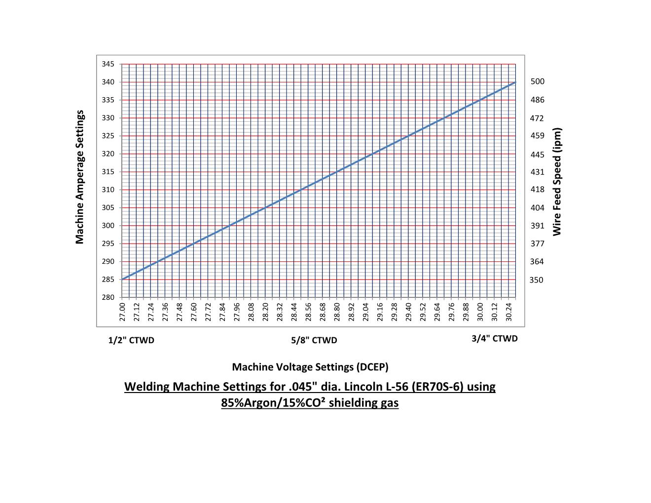
I gotta know...the chart, tell me what program you created that in. I tried to duplicate this chart in Excel but it didn't want to handle all of this info in one chart...is the CTWD/Voltage line overlaid onto a chart with WFS/Amperage? If so, how do you get the CTWD/Voltage line to also correlate to the WFS/Amperage chart?

I understand the data points come from the electrode mfg's recommended ranges, so I tried to use that data to create a chart like yours, but to no avail.
Parent - - By jwright650 (*****) Date 02-24-2015 15:18
I did this in MS Excel, the chart is computer generated however I added labels for the WFS and CTWD...couldn't figure out how to get Excel to add those onto this chart for me.

I want to eventually add a visual reference like this to my WPSs to help the welders using the WPSs. Generally I list the amperage and voltage ranges, but this is just to comfort AISC auditors....BUT...then I have to train the welders how to check and be sure that they are welding within the  WPS when the gages are broken on the wire feeder. I feel like Al is on to something in his article in Inspection Trends, so I'm trying to add this visual help to my WPSs.

Here is the one I piddled with this morning.
Attachment: L56machinesettings.pdf (30k)
Up Topic Welding Industry / Technical Discussions / Contact Tip to Work Distance "CTWD"
1 2 Previous Next  

Powered by mwForum 2.29.2 © 1999-2013 Markus Wichitill