Not logged inAmerican Welding Society Forum
Forum AWS Website Help Search Login
Up Topic Welding Industry / Inspection & Qualification / Flare Bevel Groove - Underfill?
- - By TimGary (****) Date 01-22-2016 13:34
My question is-

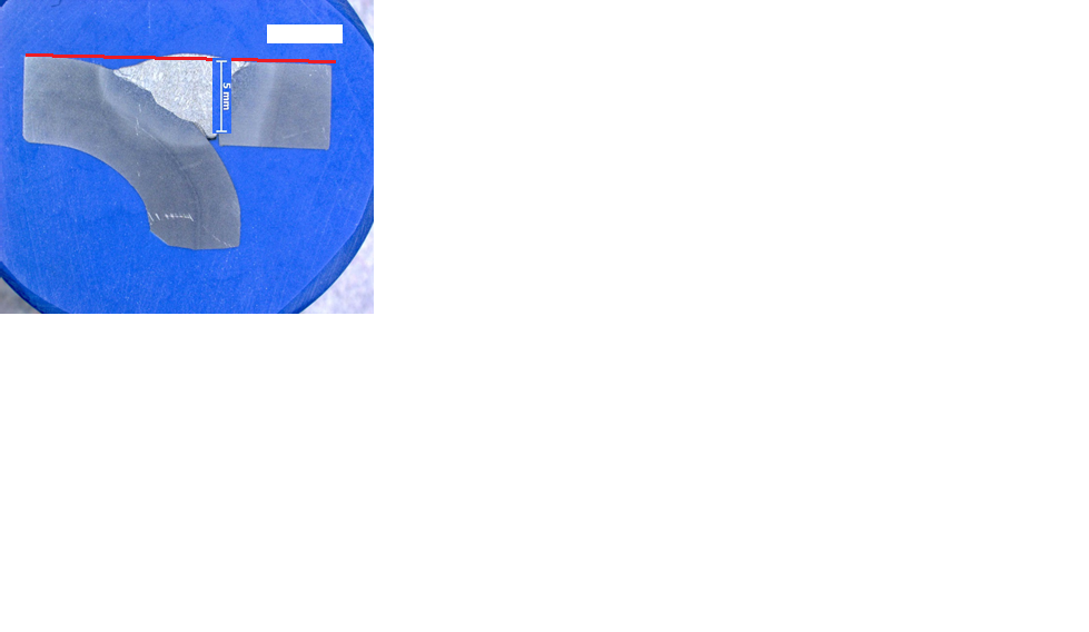
Is this partial joint penetration flare bevel groove weld on a square tube connection rejectable for underfill in accordance with AWS D1.1?
Can you qualify your answer with an applicable code section?

Additional info -
The required 5mm weld size (throat) in this 6mm thick material has been met.
The weld face width falls short of the radius line on the tube corner.
Parent - - By Lawrence (*****) Date 01-22-2016 14:10
Just some quick thoughts Tim,

Not making a pronouncement :)
Parent - By Lawrence (*****) Date 01-22-2016 14:21
.
Parent - - By TimGary (****) Date 01-22-2016 14:50
Thanks for the reply Lawrence!

While the question appears simple. I'm finding it very frustrating to nail down.
The 2.4.1.4 reference is for mathematically determining the effective size of a FBG weld. The fact that it includes underfilled welds, alludes to that this condition may be acceptable.

The 6.1 visual inspection acceptance criteria does not define underfill, other than to reference that weld profiles shall be in conformance with 5.24, which does not include a detail of flare bevel grooves. (at least in the 2010 version I'm looking at, don't have a 2015 yet).

My interpretation is that if the groove is not filled at least flush to the radius line of the tube, it is an underfill defect. This causes me a lot of trouble as the ASTM tolerance for tube radius dimensions is quite broad, and corner radii not only varies from tube to tube, but on corners of the same tube.

I keep hearing from multiple sources that filling to the radius line is not required, which is making me question my judgement as too harsh, so I'm looking to my peers for clarification.

Thanks,
Tim
Parent - By Lawrence (*****) Date 01-22-2016 15:18
You have mail
Parent - - By jwright650 (*****) Date 01-22-2016 15:35
Guys,
Nice pics and illustrations :cool:

Tim, it is a partial pen.

IMHO, I think if you have the required 5mm, it's done. (my opinion, no reference back up)
With a regular groove partial pen weld, I would agree with your requirement to be flush at the cap.
Parent - By TimGary (****) Date 01-22-2016 19:48
Thanks John.

Yup, PJP, and should be flushed out.

Tim
Parent - - By pipewelder_1999 (****) Date 01-22-2016 18:46
Based upon the fabrication requirements of AWS D1.1 as indicated in Para 5.24.3 the profiles for groove welds and reinforcement must meet the requirements shown 5.9 and 5.10 which refer to profile sketches in fig 5.4. In all cases, underfill is noted as unacceptable regardless of measurements.

However if the designer/engineer specified the joint to meet a specific profile other than that indicated within D1.1 I would expect them to provide the acceptance criteria.

With the variation in radius (unless root opening dimensions based upon radius are provided) being the deciding factor in the effective throat, allowing variations in which the effective throat varies can compound the variations that you get in production.

As an inspector, I would typically be interested in the fabrication requirements and acceptance criteria quoted within the code. If the designer/engineer has decided that a condition as you have shown above is acceptable, thats fine. He/She should specify somewhere that the groove weld does not need to be filled all the way. he has an entire chapter designated to him/her in D1.1.

There is no "Acceptance Criteria" for what you show above since what you show above could not be verified by inspection of completed welds and I am pretty sure D1.1 does not address macro on samples other than for qualification. Of course what you show would be detected visually as far as the underfill goes. In no case I am aware of is there a statement that says, "..if ya got enough penetration sometimes, its ok to not fill the joint all the way as long as you think the penetration is deeper than needed. " 

Another thing I would consider is the joint. If prequalified, the effective weld size is based upon the weld being flush. If it were qualiifed by testing, the testing should reflect the abilty for the procedure to obtain the required weld size with a given amount of underfill based upon some given fitup dimensions (Root Opening, Radius etc)

Of course all the above is an opinion and subject to being changed if the info is correct. If there were questions, I would consult the engineer. That's why they learn all that smart stuff!

Have a good day. I myself am on my 3rd SNOW DAY and do NOT feel bad about it!

Gerald
Parent - - By TimGary (****) Date 01-22-2016 19:47
Thanks for the comment Gerald.
If I'm interpreting correctly:

The weld is rejectable to AWS D1.1 Table 6.1 visual acceptance criteria for Underfill.
The Engineer can make an exception for this case provided it's documented, with tolerance quantifications, and agreed upon.
If the Engineer were smart, he/she would not make an exception without a qualified weld procedure in hand that represents the exception circumstances.

Sound about right?

Hope you and Sammy are having fun in the snow!

Tim
Parent - By pipewelder_1999 (****) Date 01-22-2016 19:48
That's how I would feel about it.
- - By 803056 (*****) Date 01-23-2016 00:26
All prequalified flare bevel and flare V-groove welds are partial joint penetration.

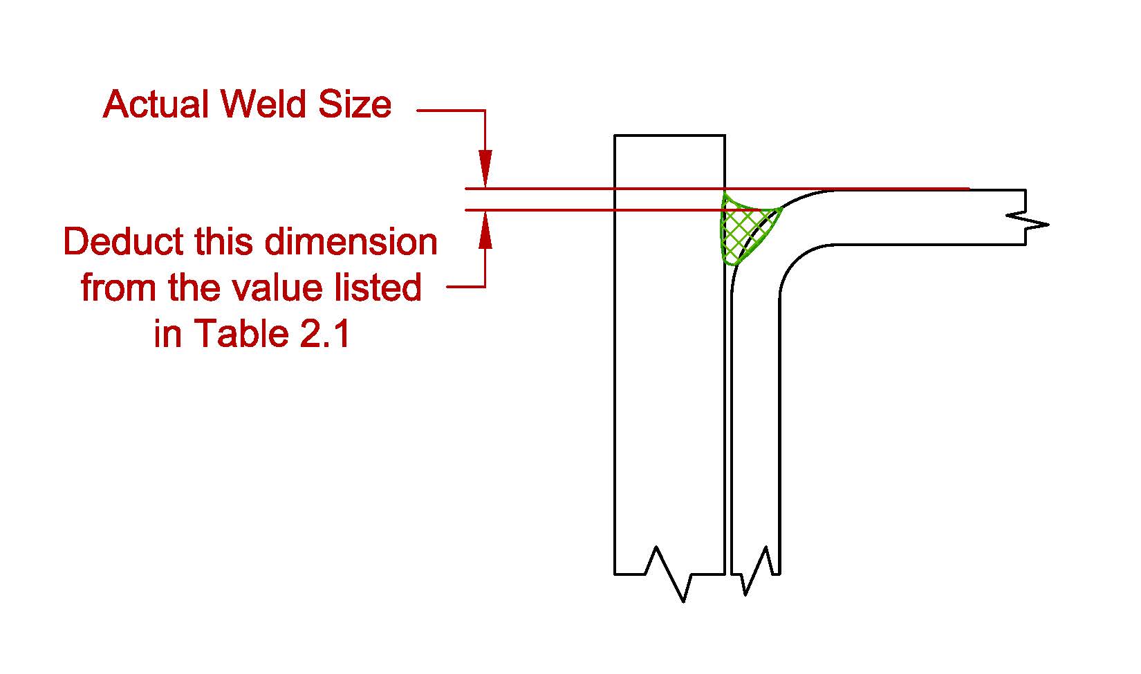
One can simply go to clause 2, Design, look up the requirements for flare bevel and flare V-grooves. It will in turn reference a table, Table 2.1 if I remember correctly. The table will provide the user with the maximum prequalified flare groove weld size as a function of the radius. Example; SMAW - flare bevel - 5/16 times the radius. flare V-groove - 5/8 times the radius; provided the groove is filled flush with the surface of the adjacent base metal.

The contractor does have the option of qualifying the WPS by demonstrating a larger weld size can be deposited.

The underfill is simply subtracted from the assumed maximum weld size listed in Table 2.1.

It looks like I'm stranded in Pittsburgh for a few days. It is amazing what a few inches of snow can do. I may not get to Houston this week after all.

Best regards - Al
Parent - - By welderbrent (*****) Date 01-23-2016 02:44
What?  Forgot your snowshoes?  :lol:

I thought they were standard issue in those parts.

Hate to rub it in... :confused: .. but we are suffering with over 70°F weather here in the valley of the sun worshipers. 

Brent
Parent - - By 803056 (*****) Date 01-23-2016 03:15
I have my snowshoes, but someone forgot to put snowshoes on the airplanes!

I might have to take a train back to Connecticut. Last year I was stranded in North Carolina for four days, same reason.

Airplanes, cars, there is a lot of similarities. I've been in airports where a few snowflakes sends them into lockdown mode. And then there's Buffalo where they pack the snow down and take off and land whether it is snowing or not!

It isn't just a job, its an adventure!

Al
Parent - - By ssbn727 (*****) Date 01-24-2016 12:52
This is what the planes at JFK look like. :eek::eek::eek:
Parent - By 803056 (*****) Date 01-24-2016 15:51
So, that's where they hid my plane!

They cancelled my flight back to Connecticut three times this weekend.

Who knew they would need metal detectors to find where the planes were buried!

How are you Henry? Doing better I hope. I haven't been home long enough to change my skivvies. You can only turn and flip a pair so many times.

I fly into Connecticut tomorrow at noon and out to Houston the next morning. Barely enough time to shovel the side walk.

Best regards - Al
Parent - - By TimGary (****) Date 01-25-2016 13:16
Thanks for the input Al.

I understand what you mean about weld size, and partial penetration.

Does this part of your reply-
"...provided the groove is filled flush with the surface of the adjacent base metal."
Mean that you would reject the weld in the picture above for underfill, or profile?

Thanks,
Tim
Parent - - By 803056 (*****) Date 01-25-2016 15:03 Edited 01-25-2016 15:12
The size derived from Table 2.1 is the maximum size the designer can assume unless the contractor qualifies the WPS for larger welds, i.e., more penetration. If the weld size is less than the minimum permitted based on Table 2.1, it can still be accepted if the max. size minus the underfill is at least equal to the size specified by the drawing.

If the drawing specifies the largest size permitted by Table 2.1 and it is underfilled, it is undersized and non compliant. It is up to the Engineer or the designer to determine if it is large enough to be accepted or too small to carry the applied load, in which case it is rejected.

I rarely reject welds that are undersized. I simply report the weld as noncompliant, list the nature of the problem and leave it for the Engineer to make a decision. It is the Engineer's call to determine whether noncompliant welds must be corrected or if they are sufficient for the applied loads. Few CWI have the ability to calculate the size of the weld required and even if they do, they are not the individual that has the authority to say, "Good enough!"

When reporting deficient welds, it is important to provide enough information that the person charged with making the accept/reject decision can make a proper informed decision. An undersized weld is a good example of what I mean. When I report a weld that is undersized, I include the actual size of the weld and the length of the weld, disregarding cold starts or unfilled craters. In many cases if the weld is longer than that specified by the drawings, the undersized weld is still capable of transferring the applied load. If the weld is undersized and no extra length is provided, the weld may be insufficient to transmit the applied loads. Providing the Engineer with all the information is essential for him to make a decision whether to accept the weld "as is" or require the contractor/welder to correct the nonconformity.

There are situations where the weld is simply noncompliant and it has to be repair. That is the typical case when drawings have been reviewed and accepted by the customer. It is more economical to correct the deficiency rather than go through the process and paperwork of getting the noncompliant weld accepted by the customer. After all, there is a reason why we use drawings. If the contractor can't follow the drawing, maybe it is time to consider a different contractor.

In other cases the assembly is designed in-house, fabricated in-house, and delivered to a customer as a completed unit. There may be some flexibility, but still there is a reason we use drawings. Quality Control has a responsibility to ensure the welds meet the drawings. If the problem is one welder, it must be addressed. If it is a problem with the design, then it has to be directed to the engineering department so it can be addressed and the drawings changed.

The inspector's job is to report his or her observations to those that have the authority to institute change. The authority extended to the inspector is dependent on the situation and the circumstances. The in-house QC inspector is probably in the best position to effect a change by either pulling the welder's qualifications if justified or initiating a design change if it is warranted.

The verification inspector's authority and responsibilities are severely limited by the D1.1 structural welding code. The scope of his or her responsibility must be clearly defined by the Engineer and the statement of special inspections. A verification inspector can easily over step the limits of authority delegated by the Engineer and find himself is deep do-do.

Best regards - Al
Parent - - By TimGary (****) Date 01-25-2016 15:47
Well said Al, absolutely and I agree with you 100%, but I don't think we're on the same page, probly because I haven't been 100% clear.

For this case, let's forget about weld size, PJP and CJP, because unless a Visual Inspector has access to the joint root, inspection is limited to VT of weld face only.

If you were VT'ing product and saw welds with faces like the one exampled through the cross sectioned picture above, would you accept or reject based on D1.1 visual inspection acceptance criteria?

Tim
Parent - - By 803056 (*****) Date 01-25-2016 17:08
No, because the assumption with D1.1 with regards to partial joint penetration, the expected joint penetration is achievable if the constraints on weld size are observed. The weld size is relatively conservative in AWS D1.1.

Your argument holds true with any partial joint penetration groove weld. That is, one can only see the weld face, not the joint penetration. There is an assumption by D1.1, based on a 100 year history of welding, that the joint penetration is achievable if the parameters of the prequalified joint are observed.

Partial joint penetration groove welds are prequalified if the size limitations are observed. That is why the weld size of a PJP bevel groove weld is 1/8 inch less than the bevel depth if the groove angle is less than 60 degrees. Likewise, there is no assumption the weld penetrates to the point of tangency when depositing a flare bevel groove. Experience has demonstrated joint penetration and the (limited) weld size is achievable if the welder has demonstrated the minimum skills required to pass the requisite welder performance tests prescribed by AWS D1.1. In reality, a high percentage of welders actually achieve a bit more penetration that that assumed by the code. While the code assumes there will be 1/8 inch incomplete fusion at the root of a 45 degree bevel, most welders will have about 1/16 to 3/32 inch of incomplete fusion in the root. Let's call it a safety factor.

When designing a flare bevel groove weld, I do not specify the maximum weld size if it is not needed. As such, a flare groove weld that is slightly undersized is not automatically declared noncompliant. However, if the maximum weld size is specified by the drawing, any flare groove weld that is slightly under flush with the adjacent surfaces is noncompliant. This is especially the case when the weld is required to be ground flush. While undercut is acceptable within limits, underfill is not acceptable if the weld size is affected.  

A little fore though on the designer's part can make a major impact on the contractor's bottom line.

Al
Parent - - By TimGary (****) Date 01-25-2016 18:47
Thanks Al, I agree with everything you've said.

Not trying to be obtuse, but would you please comment on the attached visual aid?

Thanks,
Tim
Attachment: GrooveWeldProfiles.docx (82k)
Parent - - By 803056 (*****) Date 01-25-2016 18:55 Edited 01-25-2016 19:06
No disagreement; underfill in a groove weld is a nonconforming weld, however, let me direct your attention to clause 2.4.1.4 (2015 edition of D1.1) that includes provisions for an underfilled flare groove weld. Text over-rides figures in the grand scheme of all things AWS. The provision had been unchanged for many years, so you will find it in many earlier editions of D1.1.

I would draw a sketch, but my new edition of AutoCAD is driving me crazy. I was forced to buy a book so I can learn to use it. It is upsetting to me to have to learn an old trusted program all over again. Having said that, I may be able to locate an old sketch because we have discussed in the recent past. Found it!

You are not being obtuse, your putting up a good argument for your case. Nothing wrong with that. That how we are forced to consider different perspectives and that's how I learn.

Best regards - Al
Parent - - By Lawrence (*****) Date 01-25-2016 19:59
Did I not suggest as much 18 posts ago ?

:)

With PowerPoint !
Parent - By 803056 (*****) Date 01-25-2016 20:17
I didn't go back to the original post, I found the sketch in my AutoCAD files.

Just received a notice from American. Another canceled flight out of Pittsburgh! That's about the fifth canceled flight on this one trip.

Best regards - Al
Parent - - By TimGary (****) Date 01-25-2016 21:49
:confused:
Yup, your right Lawrence, we've come full circle...

Final position...

1. Thanks to AWS D1.1: 2015 section 2.4.1.4, I know how to determine the effective size of an underfilled flare bevel groove weld, not if it's acceptable, but how to measure it.

2. Thanks to tables 6.1 and 9.16, as well as section 5.23 and figures 5.4 and A.5, I know that the visual acceptance criteria for flare bevel groove welds must not be very important because it sure as heck not defined, but now I can argue either for or against filling the groove with weld to the radius line, and win either way.

3. I agree with Al, "Save a life - burn your D1.1"

4. What it all boils down to in the end is that notches on material surfaces cause stress risers that weaken strength properties, and underfilled grooves have surface notches. The deeper the notch and sharper the notch angle, the more strength is lost.

5. I can determine an acceptance range myself by welding PQR test plates and face bending coupons with various depth underfill notches until I find the failure point, but I will have to do a lot of tests to cover the material grades, thicknesses and welding parameters I need.

6. After I complete all of the tests, I can write job instructions and acceptance criteria that few will be able to understand or follow, and anyone with a D1.1 can argue against.

7. Therefore, I shall reject underfilled flare bevel groove welds.

8. I need a beer...

Tim
Parent - - By Lawrence (*****) Date 01-25-2016 22:00
You make it sound so.... so... complicated
Parent - By TimGary (****) Date 01-26-2016 12:54
I hear you Lawrence, I wish it weren't so.
It's due to a combination of ambiguous AWS code requirements combined with very stringent yet still ambiguous requirements from multiple Customers, all with their own specifications and opinions.

Tim
Up Topic Welding Industry / Inspection & Qualification / Flare Bevel Groove - Underfill?

Powered by mwForum 2.29.2 © 1999-2013 Markus Wichitill