
darren,
I must truly admit, in particular you and Ray (Kix) are two of the colleagues who are having the right "feeling" for asking tremendous interesting questions on the one hand (it is always an enjoyment to ponder on these) but as well you're having the expertise of answering tricky questions on the other hand!
Really great!
Since I have read:
"... the centerline of fusion is the line in the center of the face of a fillet weld when pure spay mode is used in gmaw..."
and
"...gmaw spray fillets are subject to failure along this line..."
as well as I saw your drawing and the Ed Craig pictures a thousand of different ideas shot through my head. I truly hope that I will be able to write down what my humble thoughts on this are and hopefully I will find a way to not treating the item "too theoretically".
I will try...
Before I'll typewrite down what kind of "mental chaos" your question has initiated in me I would like to state that I would not agree with the different sources who have told you (I hope that I have interpreted this correctly) that the "zipper" is the cause for an increased joint's failure risk.
But...
It is of course as usual. "Normally" the "zipper" should not increase the risk of failure but this implies - likewise as usual - that the exception might not prove the rule.
What does this mean..?
I am honest. As having welded a couple of meters of GMAW seams in my life I have certainly recognized the "zipper" or let me further better say the "centerline" on steel fillet welds been carried out under using high arc or wire feed performances, respectively. And I am sure that many others have likewise seen these centerlines. To be honest as well, I have indeed considered generally what the reason(s) for this phenomenon might be before you have asked your wonderful question, but I must admit that I have never considered this topic that deeply as I did it since I have read your post. Therefore my hearty thanks, Darren!
O.k. firstly I have founded my thoughts on this on my past considerations, this is that the "cutting" effect of a GMA spray arc generates the centerline.
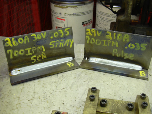
But you, Darren, did something very "strange" and extraordinary good. By following the initial post of APM you posted a particular Ed Craig link showing two fillet welds. One pulsed- and one spray arc welded one. And hereby you switched something in my tiny brain and I started to overrule all ideas on the creation of the phenomenon "centerline" I had before in order to restart my considerations quasi from ground zero. As I had mentioned in a previous response, the Ed Craig picture was very informative.
The first idea I had when I saw the picture was "Hey, that's quite interesting! Both fillets were welded by using a 0.9 mm wire diameter and 700 inch/min. (~ 17.8 m/min.) wire feed speed." I must admit, I had not the time to have a closer look upon Ed Craig's website furthermore (to much work currently) and thus I don't know if he explains what has (technically) been done there and why the welds have a different appearance, but nonetheless I have seen that - although the wire feed speed was equal - different electrical parameters were observed. What I do not know as well is the answer on the question: "Why is the pulsed arc welded fillet (although apparently the throat of both welds was approximately similar) shorter than the spray arc welded?" Were the welding times different? O.k. then the distinct lengths were of course understandable. But what, when the welding - or "arc burn" - times were equal? Then I must admit I would have a problem in understanding. Why, then I would ask, are the lengths of both seams different although the wire feed speeds were similar?
You know what I mean?
Let us - for a better understanding - take two values:
1. Wire feed speed = similar and constant
2. Welding time = similar and constant
And now let's use this by taking an arbitrary value for the welding time.
Let's say:
· Wire feed speed = 700.00 inch/min (= 17.780 mm/min)
· Welding time = 60 [s] = 1.0 minute
· Wire electrode diameter (d) = .035" (~ 0.9 mm)
This means, that the wire electrode is going to be molten down for 1 minute and we want to know the volume of the weld deposit for even this 1.0 minute.
Thus we can say (by using the equation for the volume of a cylinder):
V = Pi*r^2*h
Here is:
V = volume of weld deposit of 1.0 minute
Pi = 3.14
r = d/2
h = length of wire electrode molten down in 1.0 minute
and thus:
V = Pi * 0.45[mm]^2 * 17,780[mm]
= 3.14 * 0.2025[mm^2] * 17,780[mm]
= ~ 11,305 [mm^3]
= ~ 11.305 [cm^3]
What we have is thus a constant weld deposit volume of approx. 11,3 cm^3/min which has to be distributed over 1 minute to the fillet joint welded.
Would you agree with me when I say: " If both arc modes (spray and pulse) were processed with similar (mechanical = wire feed speed) values, as to be seen above, and both welds have thus a similar weld deposition rate (spatter losses should be neglected herein) would it then be reasonable to expect the similar (theoretical) throat and - presuming a similar welding speed - a similar weld length?"
I would say: "Yes!"
But now one might say: "Haha, have a look upon the different electrical parameters! These were not similar! And thus there must be a difference between the pulsed arc and the spray arc welded seam, and the centerline is even the proof for this difference!"
And since I know that I myself would have been a candidate for even such a question, it was the reason for me to choose the "indirect route" over the deposition rate to having a chance to (again) talking about the "electrical values" of either the spray- and the pulsed arc.
I hope you may forgive me this way and to not treating directly the question in terms of the "zipper", but (you know me) I hope as well that I'll be able to show you finally that the above mentioned has strongly to do with even your question.
Taking the Ed Craig picture and taking thus the electrical values of both arc modes been used for welding the seams. Here we have:
· Spray Arc: 260 [A], 30 [V]
· Pulsed Arc: 210 [A], 29 [V]
"Hmmm, very interesting!" that was my very first thought when I saw the picture. Why...
Well, since I thought by myself:
"When we do have two fillet joints having a quite similar outer appearance (as far as possible interpretable from the picture due to not knowing any particular details), i.e. theoretical throat, wire feed speed,..., how, so I asked myself, could these similar appearances been generated by that significant different electrical values?" And further I asked myself of course: "Which value of welding performance do these different parameters yield when calculating even this performance?" So I have used the standard calculations for electrical power to deduce on the thermal energy input into the base material (you know, my major goal was and is - animated by you - to find out where the centerline does come from, what kind of physical phenomenon it actually is and if this phenomenon can increase the risk of a weld joint failure). This since I supposed that the centerline phenomenon must have something to do with the thermal energy input the base material is subjected to and since it is rather easy to calculate the thermal energy from the electrical energy. So what did I do?
We know, by allowing to simplify (neglecting the process efficiency coefficient "eta"), the electrical power can be calculated by using:
P = U*I
Here is:
P = (Welding)Power in Watt [W]
U = (Welding)Voltage in Volts [V]
I = (Welding)Current in Ampere [A]
We know as well that the ("true") spray arc mode (constant voltage assumed) shows a great constancy in both current and voltage, even since the droplet detachment and transfer occurs without any significant interruptions (e.g. short circuits) creating inconsistencies in the transient regime. By simplifying we can thus say: "Yes, the spray arc mode is characterized by "constant" transient regimes in voltage and current and thus the well-known equation can be used to calculate the electrical power of the arc in a sufficient extent.
Using the values from above:
P spray = 30 [V] * 260 [A] = 7800* [W]
(*) fluctuations and ripples to be neglected
Hmmm, now we have the power, yes, but what does "Power" actually mean? Does it mean that we do have a "7800 Watt" Arc? Actually yes. Though this value doesn't express very much accurate on the actual arc energy which is imposed upon the base material. However, this should not be treated further herein, since I guess it is more important to have a view upon the differences being recognizable when having a look upon the Ed Craig pictures showing that significant distinct electrical parameters. And thus to repeat my above question: "How can that different parameters create that similar seams - or at least similar outer appearances?"
I hope you don't mind if I make a short sidestep at this point, to trying to clarify what I pursue. It was important for me, when I have started to thinking about your question and the attached picture, to understand personally if the "centerline" does occur only in "spray arc welded" or as well in "pulsed arc welded" fillet joints.
Thus I would like to use the same equation as been used for calculating the spray arc performance for calculating the pulsed arc performance. I hope it will show that there is a main problem often to observe in using electrical values in correlation with a pulsed arc. So:
P pulse = 29 [V] * 210 [A] = 6090 [W]
??? 6090 Watt ???
Hmmm, strange, at least for me!
When I have calculated correctly (please correct me when I've done wrong!) this is 1710 W less than the spray arc performance (7800 W). And despite this fact, both arc modes could perform the - apparently - similar weld deposition rate and a - apparently - similar outer seam shape?
You know what I mean?
Well, then allow me to resume...
Apparently there must be a kind of approach of the "real" performance between the "spray" and the "pulsed" arc. By using the term "real" I try to express that the "real" welding results - as to be observable on the pictures - appear to be quite similar, although the measured values the arc performance is based upon appear to be significantly different. Thus it seems that even this approach appears to be not "captured" or "observed" by the power supply meters providing the values we can see upon the Ed Craig pictures.
O.k. o.k., now you will answer most likely: "Son of a gun! Stephan what are you bothering us with these uninteresting facts? It is well-known that the pulsed arc has a non uniform transient regime in both voltage and current and it has been already mentioned and discussed in some previous posts above!"
And yes, I would absolutely agree with you!
But...
What actually is the "true" difference then between the spray- and the pulsed arc if we can admittedly observe a difference between the measured electrical values (actually the basis for the arc performance) but not a real significant difference in the welding results?
And now I'd like to come slowly to the point.
Presuming we are using same wire feed rates in both arc modes, we can presume that even these wire feed rates (standing again for weld deposition volumes) must be "overcome" by the arc power. What does this mean? Well, in my eyes the (in this case) 700 inch of wire electrode must be molten down in a way of highest welding stability and repeatability within a 1 minute period. If the (mechanical constant) wire feed rate would not match the voltage being provided by the power source, we would observe either an inappropriate (too long) arc length (voltage too high) or an inappropriate (too short) arc length (voltage too low). Both cases are undesired since yielding either "burn back" to the contact tip (voltage too high) or - at least - spatter by short circuiting (voltage too low). In other words, if this would occur one could expect to have severe problems with our welding process.
But what are the electrical pulsed arc values we can read upon the power supply's display worth then if they appear to not reflect the true welding conditions within the arc itself? Hmmm, and furthermore could this be the reason for so many questions how to use the electrical pulsed arc values to be readable on the display for generating e.g. a WPS?
I guess... both questions are reasonable.
Thus...
When we are looking upon the transient regime of voltage and current of a pulsed arc, we can see that the equation as been used above cannot capture no more the true conditions of the arc - of course. And so we should use a more accurate way of capturing even these conditions. But I must repeat myself once again (see my previous posts on this), I would rather like - to following Lawrence' proverb: "Not physics, the rubber meets the road!" - to avoid the detailed theoretical treatment of these pulsed arc calculations herein, due to this topic is truly "spicy". However I remain by my opinion, it should finally be unnecessary to express what I think.
But nonetheless...
Let's imagine again what we have discussed formerly and thus let's recall that the pulsed arc (current) transient regime must exceed a value which is specific to a wire electrode's chemistry, diameter, shielding gas composition,..., this is the critical current value (Icrit.). As we have discussed this value is likewise to be seen as to be the specific current height at which the "globular" droplets are being significantly reduced in both size and volume and being transferred "spraying like" and short circuit free along the arc column towards the weld pool. Now one has to consider that the "true spray arc" does take place only within a tight parameter window showing a spraying low volume droplet transition across the arc column. More to this a bit later on. When we do consider now a pulsed arc this critical and specific value is exceeded and admittedly in a way that the safe transition from globular to spray is assured to be achieved. This means the critical spray arc value in the transient regime of a pulsed arc is exceeded with an "additional charge" of safety. And thus the "pulse peak" value can lie significantly higher than the actual critical "spray arc" current value. Since the pulsed arc is always a function of the frequency and this again is always a function of time, we can assume that the time period the critical current is existing is fixed in the background parameters (proprietary) but we can assume as well that the critical value is not only exceeded instantaneously but for an appropriate time range.
So what do we have by that?
Actually we have an increase in the arc performance compared with a "conventional" spray arc, whose true character exists only within a very tight window. Thus the measured performance value should be higher. But now we have the well-known transient regime of a pulsed arc. This is, the current is being decreased (by proprietary power supply controlling algorithms) along a specific period of time (fixing the frequency finally) to reach the background current level, which is much lower than the critical spray arc current value. This means the measured arc performance should be significantly lower compared with a fine adjusted spray arc. And it is.
And now by using both values we can see, that finally there must come out a mean value of both voltage and current over the course of an appropriate pulsed arc regime. And even this mean value is measured by the power supply meters and lies often significantly under the values of a "continuously" burning spray arc.
I know, there might be some of you who would now say to me: "Stephan, but these mean values are not the "true" values, since the - periodical - measurement of instantaneous values for creating finally the "arithmetic" mean does not lead to similar welding results as to be seen on the Ed Craig pictures! And furthermore it must be the area underneath a single pulse which should show the true calculated performance of a pulsed arc!"
And yes, once again I would agree with you! But even this hits the ways of calculations I would like to avoid to treat herein, thus I beg your forgiveness.
But how can the results on the Ed Craig pictures can be explained then?
Not, as apparently shown, by the - measured - lower weld performance of the pulsed arc used for melting down the 700 inches of wire electrode per minute. How then..?
Hmmm, I truly hope you have followed me up to here and I hope much more that this what I have considered by twisting my tiny brain might make any sense finally!
O.k. coming back to the topic...
Energy, as we know it, is Energy. It can't be destroyed or generated but it is there and can only change its form of appearance. And thus - in my humble opinion - with respect to our arcs, if both arcs can perform the same (melting 700 inches of the wire electrode / minute) and yield furthermore quite comparable outer welding results, the amount of "true" energy been used to maintain both arc modes should be similar finally as well.
Or not..?
I must admit it appears a bit confusing, isn't it?
But I have considered as follows.
Let us have a look upon the equation:
P = U * I
We can see the voltage (U) and the current (I) yielding as its product the power (P). But what is voltage finally?
According to Ohm's law, voltage is current (I) times resistance (R) what's the reason for that we could also write for the equation above:
P = I^2 * R
And this - at least in my humble consideration - is the whole secret. The current fulfills a quadratic function within the arc process. And hereby again the resistance heating of the wire tip to workpiece distance - or wire electrode's stick out - is tremendously risen while the drastically increase of the current significantly above the critical "spray arc" value, this should allow finally to achieve similar weld deposition rates compared with the conventional spray arc.
To find out what kind of "true" energy has been used for melting down a specific volume of filler wire by using a pulsed arc mode, one should use another way of calculation, e.g. the Root Mean Square (RMS) which captures much more accurate what's making a pulsed arc really a pulsed arc.
And quite now I have reached the point in time when I want to say.
If, if ever, the (true efficient) value of energy of a pulsed arc and a spray arc would be comparable in its total amount (from their outer welding results they were comparable as it appears - see the Ed Craig pictures) then I would like to ask:
"Could eventually both arcs (spray and pulse) generate a centerline in welding a fillet weld?"
This was thus the next question for me to consider after I have reached the level of "confusion" in my head.
And so I did thinking as follows...
I have tried for myself to mentally recall how often I have seen even the phenomenon centerline in GMAW. That was not that hard, since as I said, I have experienced it sometimes when welding with a high performance spray arc in fillet joints. But honestly it was hard for me to recall to having seen the centerline - at least consciously - in using a high performance pulsed arc. So I tried - once again - to find a welding sample in my employers company which could prove the existence of a centerline likewise in pulsed arc welded fillets. But no chance. I found nothing. What I found whereas was a welding sample showing a fillet joint welded by having used the T.I.M.E.© process and thus a high performance spray arc under a patented shielding gas (65%Ar/26.5%He/8%CO2/0.5%O2) atmosphere.
The base material's (~ grade SA 36) thickness was 10 mm (~ 0.4 inch) and it has been manually welded in pos. 2F. The wire electrode was comparable the ER 70 S6 having had a diameter of 1.2 mm (~ 0.045 inch). The welding speed achieved was 75 cm/min (~ 2.5 ft/min) by using the following welding parameters:
· Current = 400 [A]
· Voltage = 42 [V]
· Wire feed speed = 21 m/min (~ 69 ft/min)
Please have a look upon the attached Spray_Arc.jpeg. Isn't it wonderful? I mean, yes it is, since it shows exactly what you have mentioned, even the centerline or "zipper". After that I had another look upon the Ed Craig picture, to trying to recognize this centerline(s) there as well. As you have mentioned in your post, on the left one (spray arc) there seems to be somewhat similar recognizable, on the right one whereas (pulsed arc) rather not. That was a point in time where got - at least for a little moment - confused completely. Although not knowing the shielding gas composition Ed Craig has used for welding both seams (I assume it should have been a less active gas containing one due to the very little slag isle in the end crater(s)) it appeared that only the spray arc joint had a rudimentarily recognizable centerline.
Hmmm, strange. We appear to have a similar welding performance with both arc modes but we appear nonetheless to having no similar result with respect to the "centerline". That was the point in time when I have remembered - at least I tried - some high speed videos I have seen in the past of both spray- and pulsed arc. And I was nearly certain that there was actually a difference in the arc behavior.
Whereas the "real" spray arc under Argon rich shielding gases (existing even within the little window as mentioned above) has a very peculiar appearance (high current density and temperature core) the pulsed arc shows (mostly) an appearance different to this - as well when being maintained under the same shielding gas.
What does this mean? Well, when we are having a look upon the attached Spray_Arc_1.jpeg, we can see what I have tried to describe. The depicted spray arc shows a well-known bell shaped appearance. When having a closer look upon the picture one can vague recognize the small sized droplets being transferred along this mentioned hottest "path" or "core" of the arc plasma. The outer areas whereas are compared with the hot core, relatively "cold". This means strongly simplified that the droplet transition across the arc gap is accomplished along the high density core of the plasma. I have tried to find a video or somewhat comparable, please see also the attached link:
http://www.mss-schweisstechnik.de/video/sprueh.avi .
This means again that the temperature of this limited area upon the base material achieves highest degrees to enable some very, very interesting physical interactions in the weld pool. However, the most well-known phenomenon is the remarkable "finger type penetration" of a spray arc under Argon rich shielding gas compositions.
Hmmm, even this - the high performance density in the center and thus the deep center penetration - could already be the reason for the centerline on a spray arc welded but not the pulsed arc welded fillet joint... or rather not yet..?
Before I'll try to answer this question, let's firstly have a short look upon a pulsed arc. What kind of arc shape is (very often) observable when using this arc mode? Yes, a wide spread one resulting from the very steep increase in both voltage and current along the transient regime of the particular pulse form. For a better understanding please see also the attached:
http://www.mss-schweisstechnik.de/video/puls.avi .
As can be seen in this little image the arc area is widened compared with the spray arc. The actual metal droplet transfer whereas - as to be seen quite clearly - is accomplished not at the pulse peak but at a specific point (proprietary) of the pulse flank's dropping period. As a pulsed arc is working when imposed upon a fillet joint, can be seen under having a view upon:
http://www.mss-schweisstechnik.de/video/puls_keh.avi .
It shows quite good how the pulsed arc is being spread over a wider area while the pulse regime is formed (by the power supply's algorithms) compared with the "conventional" stringent oriented "hot core" spray arc.
So far so good...
So it seems accomplished and we have found the reason for the centerline upon the spray arc fillet joint but not upon the pulsed arc fillet joint - finally!!
The high dense energy core of the spray arc plasma causes the centerline. Due to the pulsed arc has admittedly a comparable arc performance but distributes the energy content in a different way to the spray arc, it even shows no centerline upon the seam surface.
Really..???
Wait a moment and see what I have found!
I have received a welding sample at the last world's greatest Welding fair "Schweißen & Schneiden" held in Essen in 2005. The sample has been performed by using a Panasonic welding robot + integrated power supply. They call it, as far as remember correctly, the TOWER principle. The interesting on this weld sample whereas is not the fine and small fillet joint seam itself, been performed by using a lowest performance s h o r t - a r c on a 1.0 mm thick base material but rather what kind of phenomenon the seam itself shows.
Yes! You won't believe it, but it shows a "centerline", please see also the attached Short_Arc_Centerline.jpeg. I beg your forgiveness by not knowing any kind of technical details, but I guess these are rather secondary. The actually astonishing is (at least for me):
"The centerline phenomenon appears to being not only a stringent spray arc fillet weld phenomenon."
This so far.
By avoiding to list hereinafter all my surely strange personal considerations on this strange experience (I don't want to kill you :-)) I'd like to come finally to an end to finally state my thoughts on your original question. So here's my try of an explanation.
I guess that the centerline phenomenon is rather not a question of the arc mode itself but rather a very particular one having to do strongly with a very particular balance of different parameters.
What does this mean?
Well, when we can achieve a physical condition of where the imposed thermal energy input stands in a very particular relation to the base material's composition + the shielding gas composition + the filler material's composition + (and this is in my opinion the crucial point) the welding speed [which must be relatively "high"] (compare the crystallization shape of both seam surfaces), then we can achieve that the centerline phenomenon may occur. Additionally to this, I guess that the heat dissipation conditions when welding a fillet joint supports the peculiar epitaxial solidification (see also Al's (803056)) wonderful explanations under:
http://www.aws.org/cgi-bin/mwf/topic_show.pl?pid=90694#pid90694) of the melt having a quasi symmetrical "saw tooth" pattern (as to be seen on the attached pictures).
In other words, besides the mentioned above, one must adjust the exact point (balance) between thermal energy input - weld pool heat content - heat dissipation - weld pool surface tension - solidification range and weld pool motion in welding direction to achieve a centerline - at least upon the seam surface.
And thus basing on these great descriptions coming from Al, I would finally reply your question if the centerline may increase the risk of failure of a fillet weld as follows:
· I would not tend to say that the centerline alone might cause an increased risk of joint failure. This due to the fact, that then all little "surface irregularities (ripples)" - caused by e.g. out of position welding (vertical up) - should increase even such a risk. But...
· If the centerline is mainly based upon an epitaxial grain solidification which can cause a severe segregation of e.g. crack raising elements, then I would recommend to have a double check how the macro- or micro-sections will look like. Since then - at least in my humble opinion - the centerline would penetrate the entire seam thickness and could thus - eventually - act as the "zipper" as you have mentioned it in your great question.
· Finally I assume that as well for the pulsed arc mode exists even the balance between the different affecting parameters - inner as well as peripheral ones - responsible for the generation of a centerline, just as it astonishingly did as been seen for the low performance short arc mode.
So far my humble thoughts on this.
Thanks darren for your patience as well as for this wonderful question and I am looking forward to what you and the others will say on this*.
Best regards,
Stephan
* Perhaps I am completely wrong by what I have considered and stated previously...
** By the way, the slight reinforcement of the pulsed arc welded fillet (compared with the spray arc welded) on the Ed Craig picture might be caused by the slightly reduced seam length, since, as I assume, the wire feed rate is similar to the spray arc welded joint, the deposition rate should be similar as well (always presumed that the welding time is similar as well!).

 IGBT Anyone?
 Forum
Forum


